Designing a Custom Server Rack
Introduction
A server rack is incredibly useful—it turns a mess of computers and equipment into a neat and organized setup. At least, that’s what I’ve been trying to achieve over the past five years. Here’s my current setup:
 My Racks Area
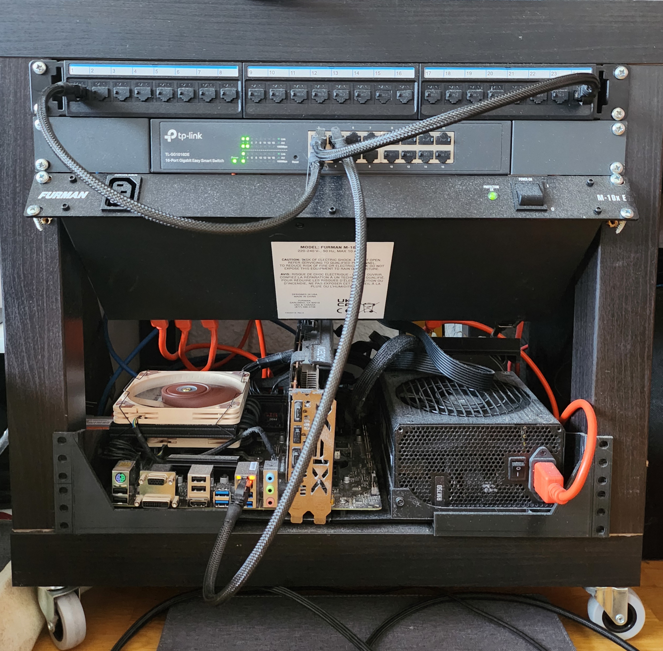 Close-Up View of my Server Rack
Warning: Be careful when screwing directly into the legs—it doesn’t hold up well.
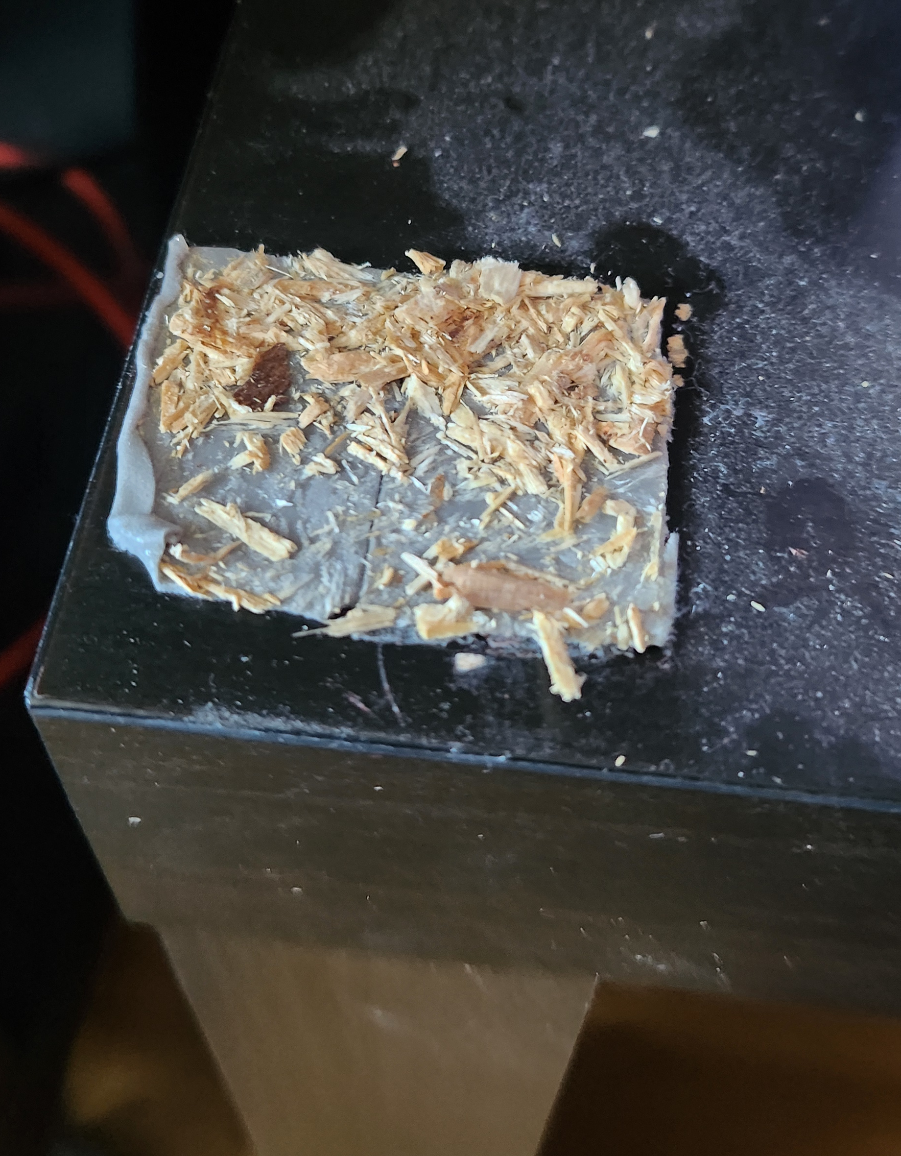 Remaining VHB Tape from the Right Rack
Yes, both racks are held together with VHB tape… I’m not proud of it. But when you don’t have wood screws or a drill, you have to get creative. I did manage to screw the wheels in by hand, though.
I got the idea of making a rack with an IKEA Lack table while shopping at IKEA. Ironically, I only discovered the “IKEA Lack Hacks” community two months after building my first rack.
Nowadays, I mostly use them for storage rather than an actual server rack, but that needs to change. As you can imagine, this was not my first attempt, and once again, it failed because screwing into the IKEA Lack legs isn’t the greatest idea. So, I searched for a better solution and found this design along with these cage nuts. However, I wasn’t happy with their designs, so I decided to create my own from scratch.
Sketching the Concept ✏️
Before diving into CAD software, I started with hand-drawn sketches to visualize:
- The overall structure of the rack.
- Mounting points for screws, brackets, and rails.
- How the cage nut adapter would be printed.
Here’s an early concept:
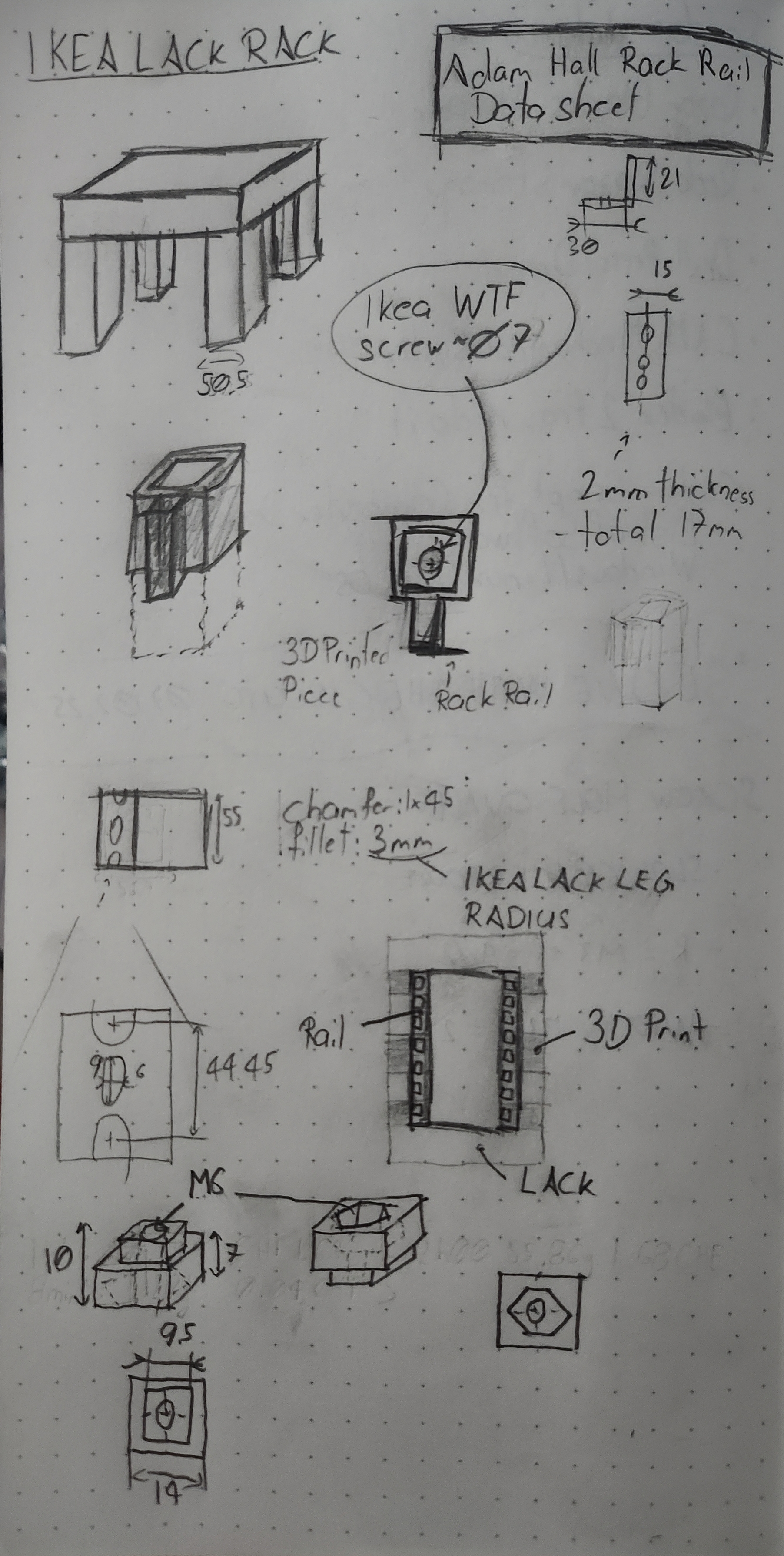 Initial Hand-Drawn Sketch
Materials & Tools Needed 🛠️
| Tools | Materials |
|---|---|
| Writing Instruments and Paper | 3D Filaments |
| Extrait de Normes 2022 (VSM) | M6x25 or M6x30 Screws |
| Measuring Tools (Ruler, Caliper) | M6 Cage Nuts |
| CAD Software | M6 Nuts |
| Google Machine | Rack Rails 18HE (18U) |
| 3D Printer | IKEA Lack |
| Screwdriver | Optional: Casters |
| Optional: Drill | (requires 16 wood screws) |
Designing & Prototyping 🖥️
Key Design Considerations:
✔ Sturdy adapters that support the equipment’s weight.
✔ Precise dimensions for mounting and cage nut adapters.
✔ Simplified assembly, avoiding too many different 3D-printed parts.
✔ Easily reproducible without requiring special tools.
✔ Visually appealing design—no ugly hacks.
I referenced the Adam Hall 19-inch rack rails datasheet for standard dimensions:
Note: Pay attention to the cotation on the bottom-left, the vertical one it’s a 9 not 6.
With this reference, I created the rack rail and cage nut adapter design while adhering to mechanical standards.
Here are the main sketches:
 Main Sketch of the M6 Nut Adapter with Sequential Bridging Highlighted
Pro Tip: Design a Sequential Bridging instead of using supports when possible. Check out this video tutorial from Maker’s Muse.
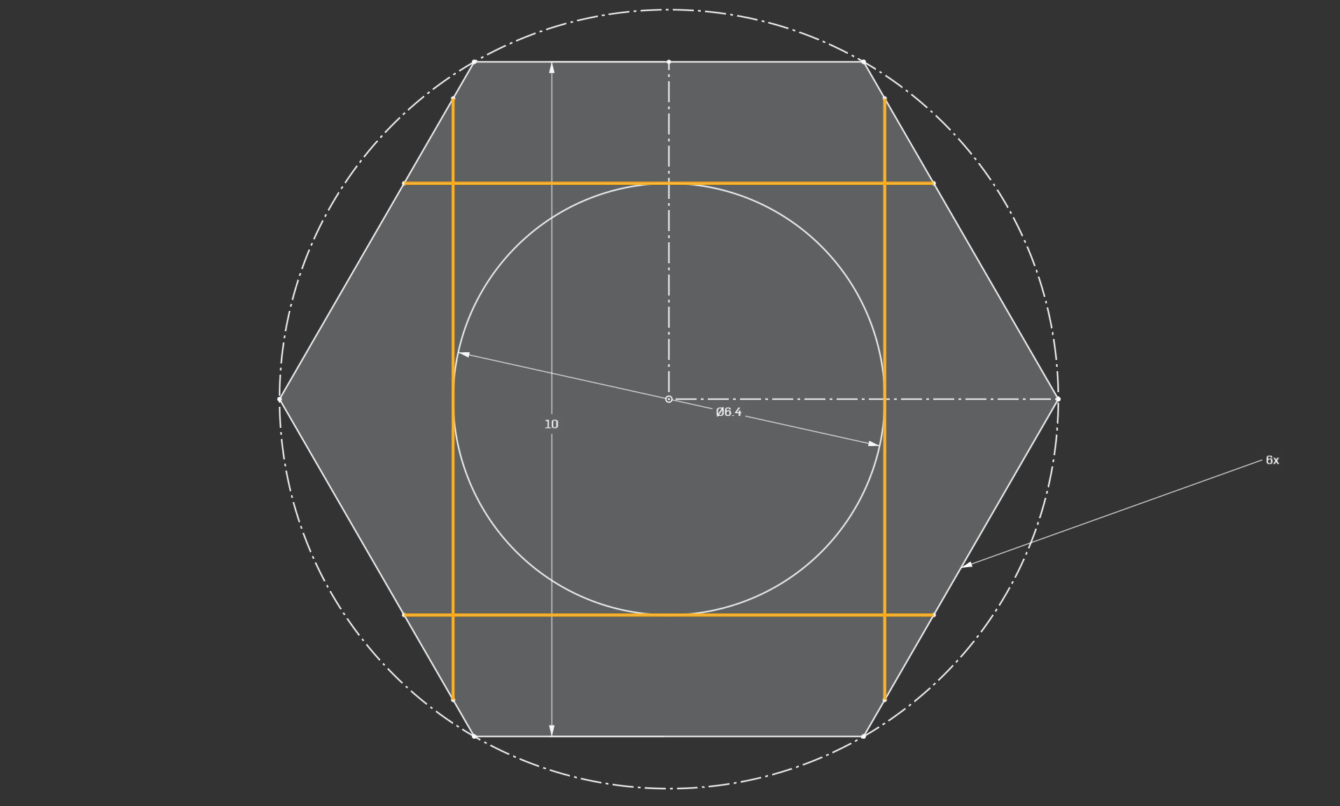
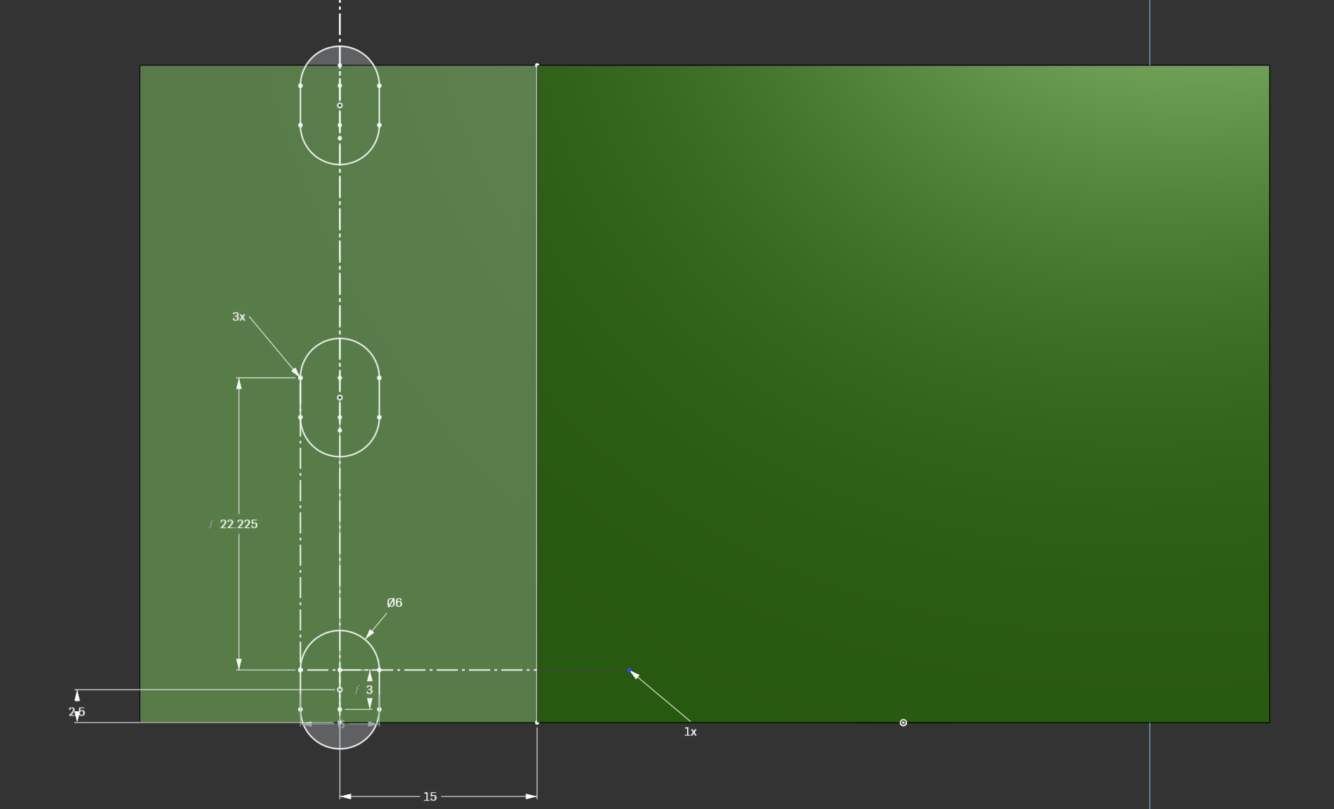 Lack Leg Mounting Holes Sketch
Pro Tip: Use Linear Pattern instead of manually copying repeating elements.
And here’s the result:
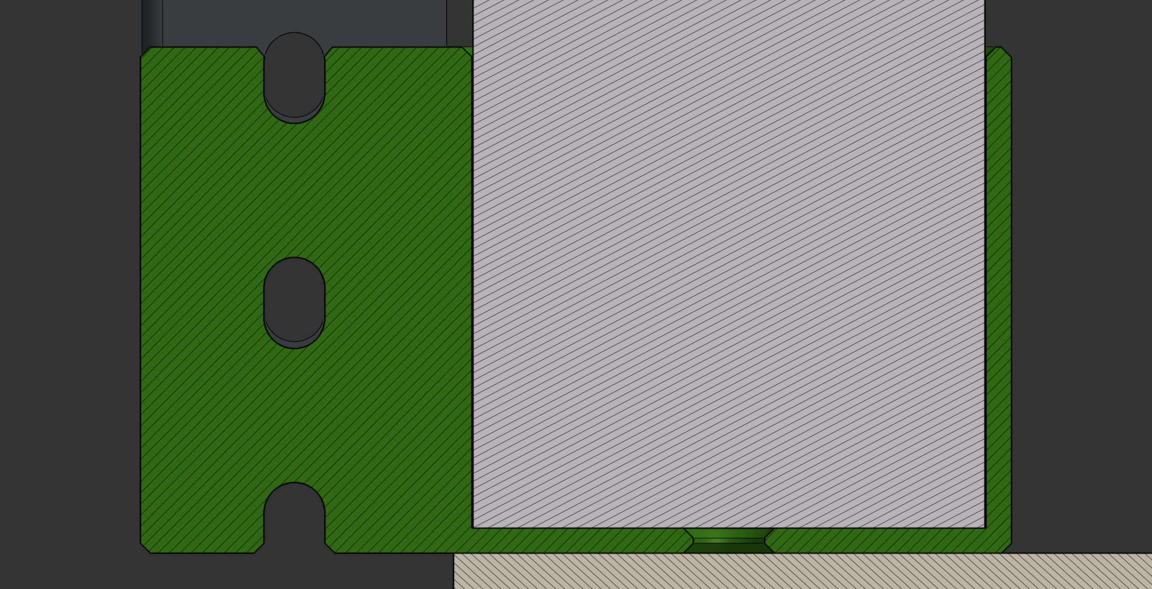
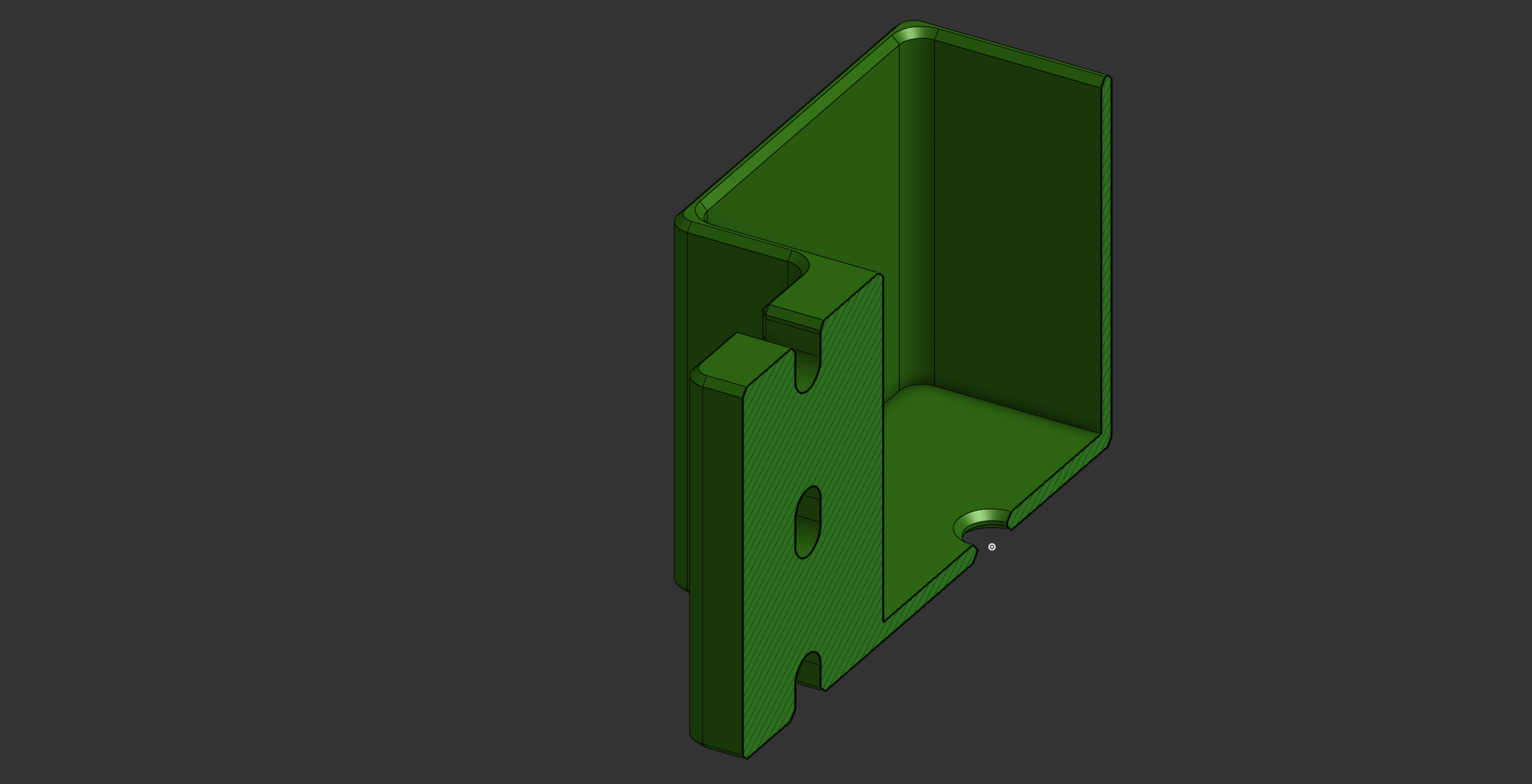 ISO Section View of Lack Leg Adapter
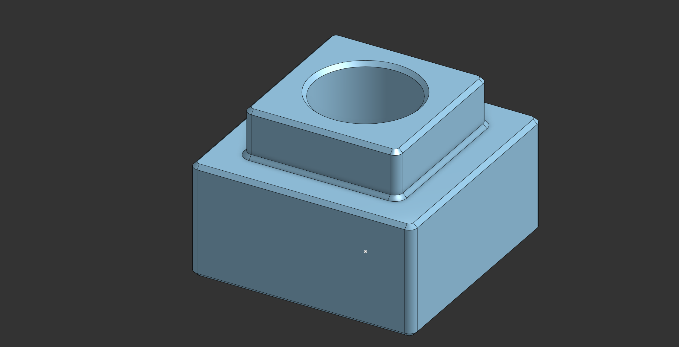 M6 Cage Nut Adapter
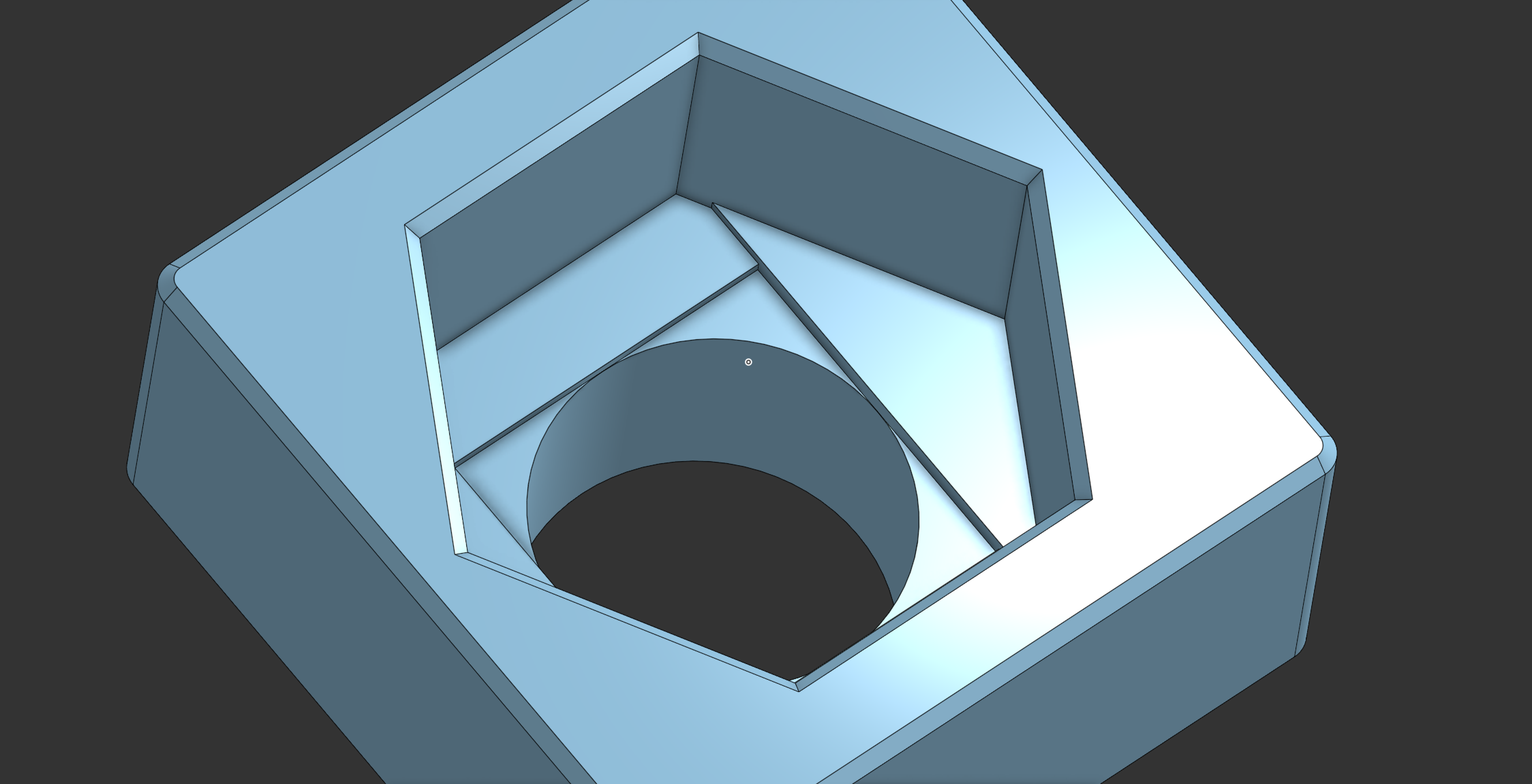 View of the Sequential Bridging
Pro Tip: When applying a Fillet or Chamfer, select an edge, then right-click
RMB→Select→ choose eitherEqual Length/Radius EdgesorParallel Edgesto automatically select matching edges, rather than manually selecting each one.
Prototypes & Adjustments
Below is the final assembly, along with key alignment and clearance checks:
 Final assembly ISO View
 Bottom Hole Alignment Check
 Mid Hole Alignment Check
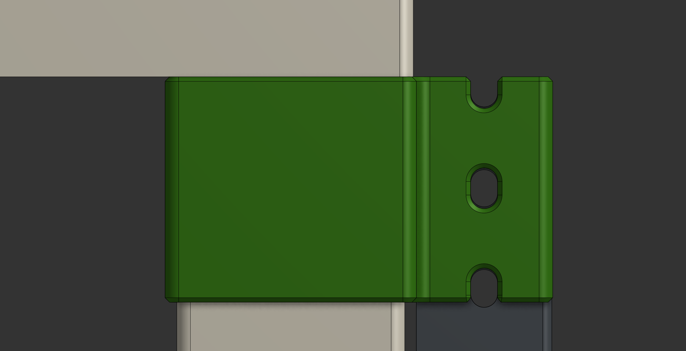 Top Hole Alignment Check
 Clearance Check
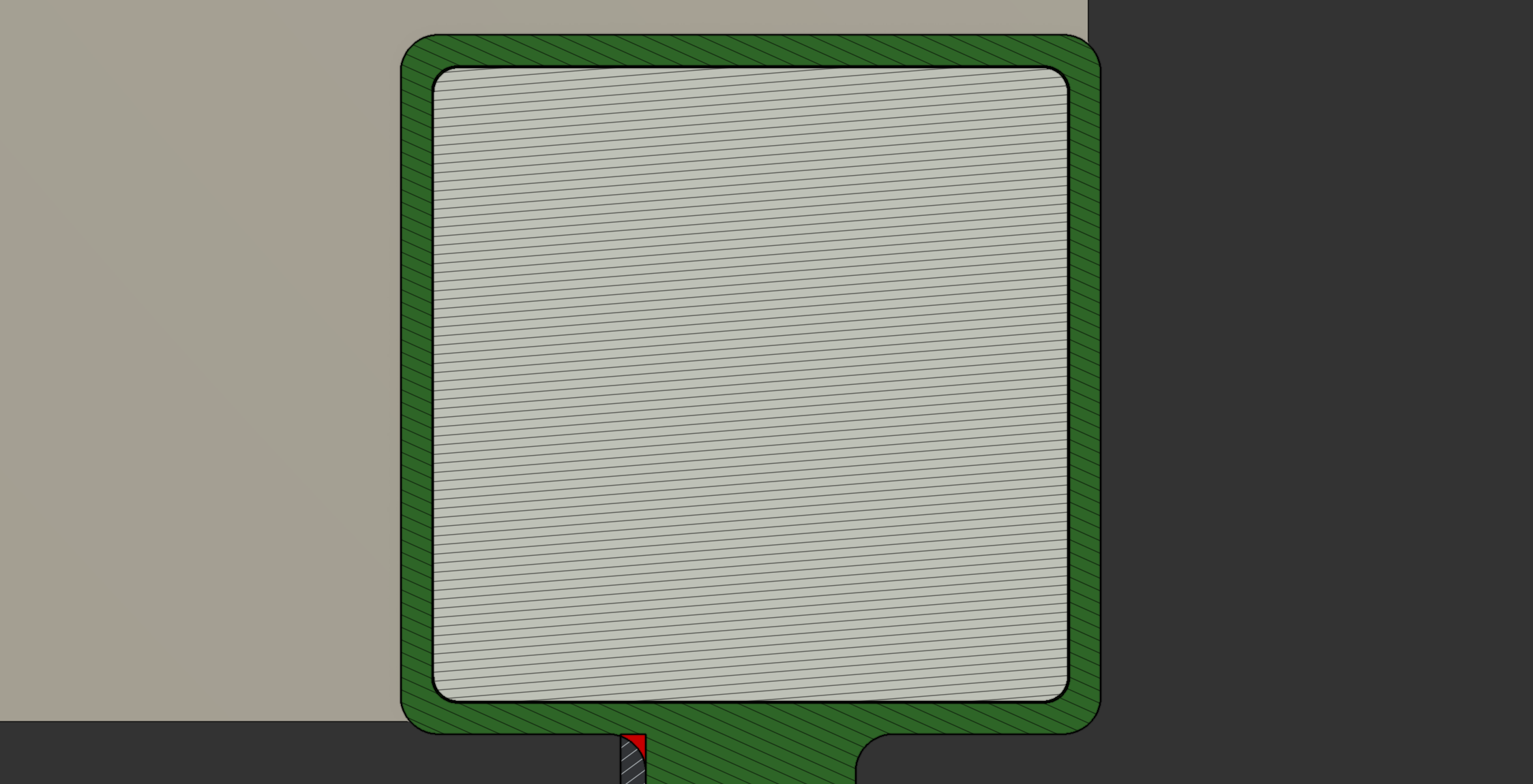 Clearance Check for Radius
Note: The IKEA Lack uses an R2 radius for both the legs and the tabletop.
3D Printing Settings
| Setting | Value/Parameter |
|---|---|
| Print Material | PETG |
| Layer Height | 0.2 [mm] |
| Infill Density | 15% |
| Infill Pattern | Cross Hatch |
| Wall Count | 6 |
| Top Layers Count | 3 |
| Bottom Layers Count | 3 |
| Support Structures | NO |
| Brim or Raft | NO |
Note: PLA can also be used, but PETG offers better durability.
Here are the printed pieces:
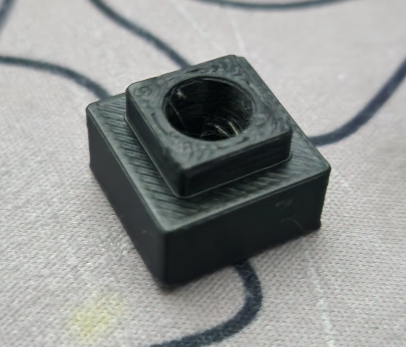 Cage Nut Adapter
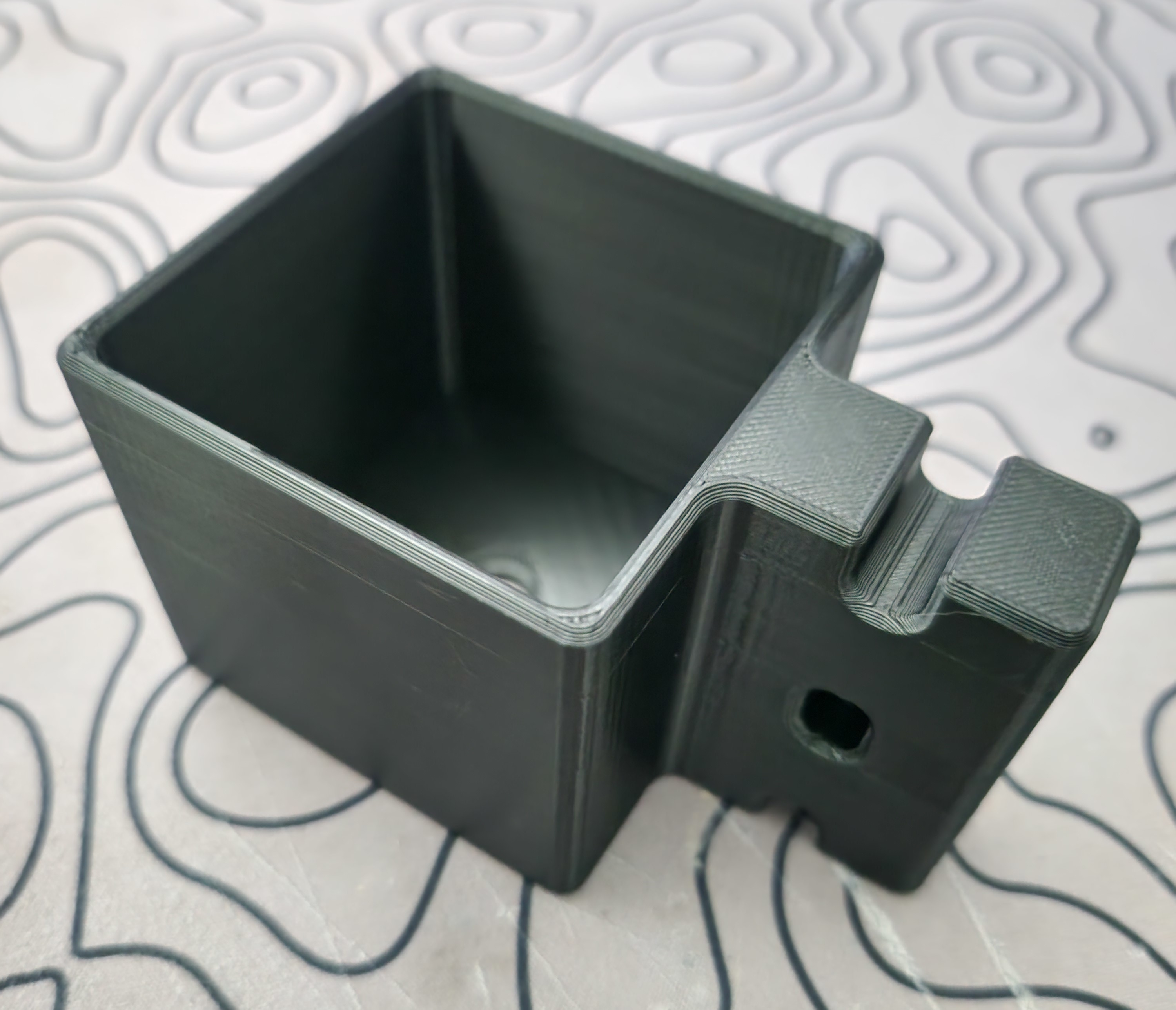 IKEA Lack Rack Rail Mount
Final Assembly & Installation 🔩
- Attach the Leg Adapters using screws.
- Stack and align the IKEA Lack tables.
- Insert the Pins into the adapter holes to secure both tables.
- Mount the Rack Rails onto the adapters.
- Optionally, attach the Casters to the bottom table.
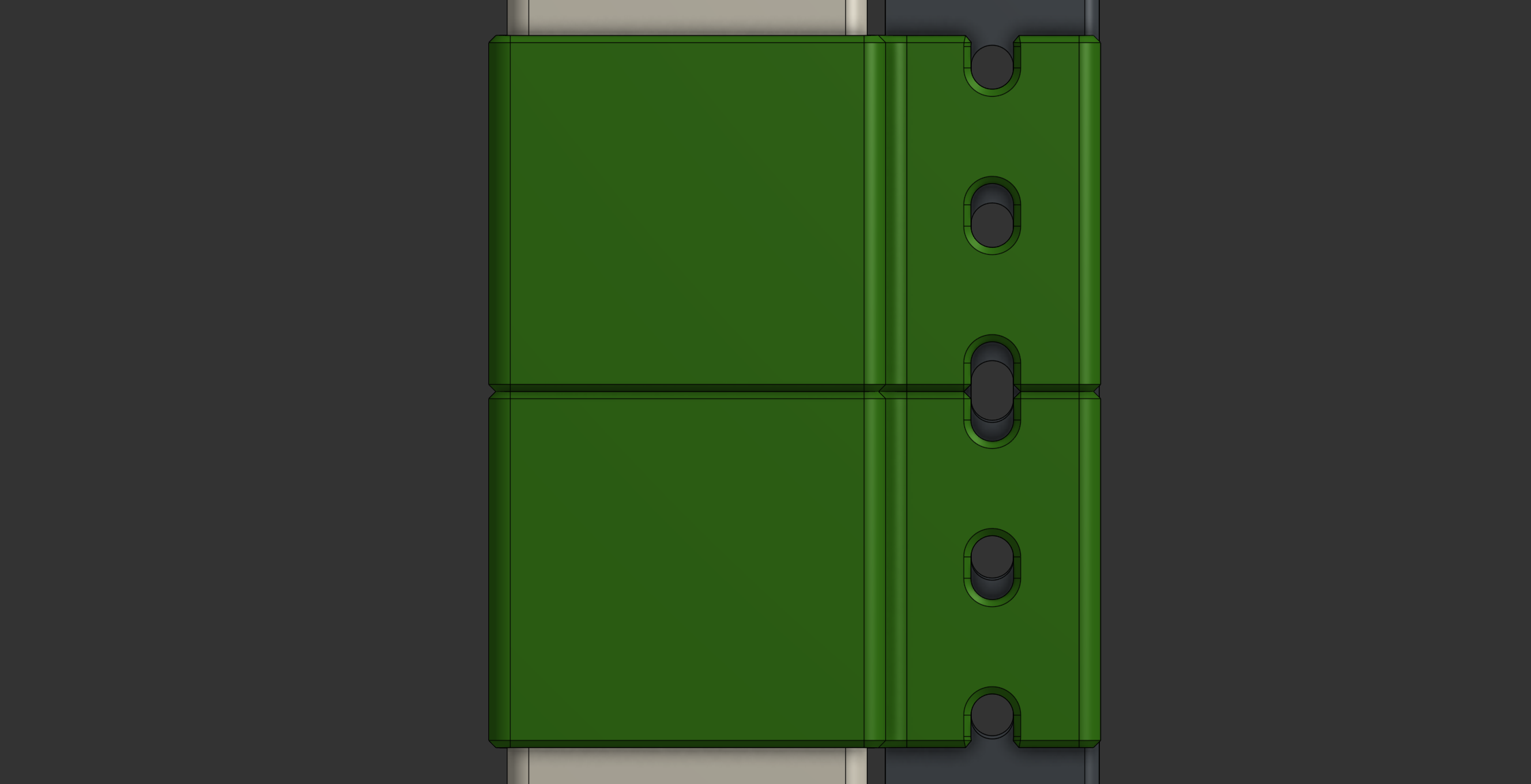
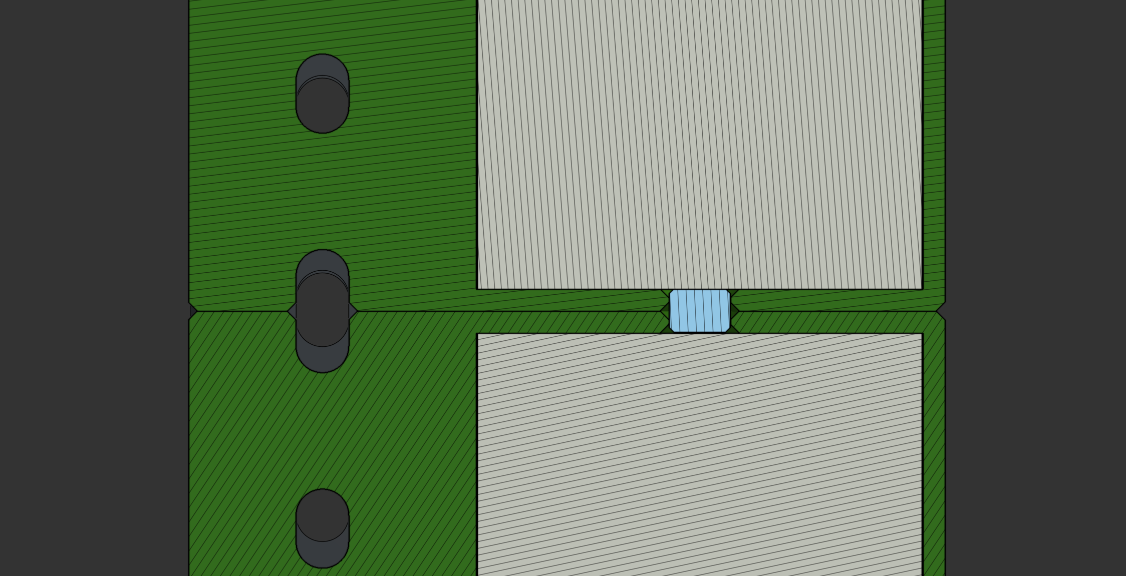 Assembly Mid-Section
Once assembled, it’s time to install the cage nut adapters:
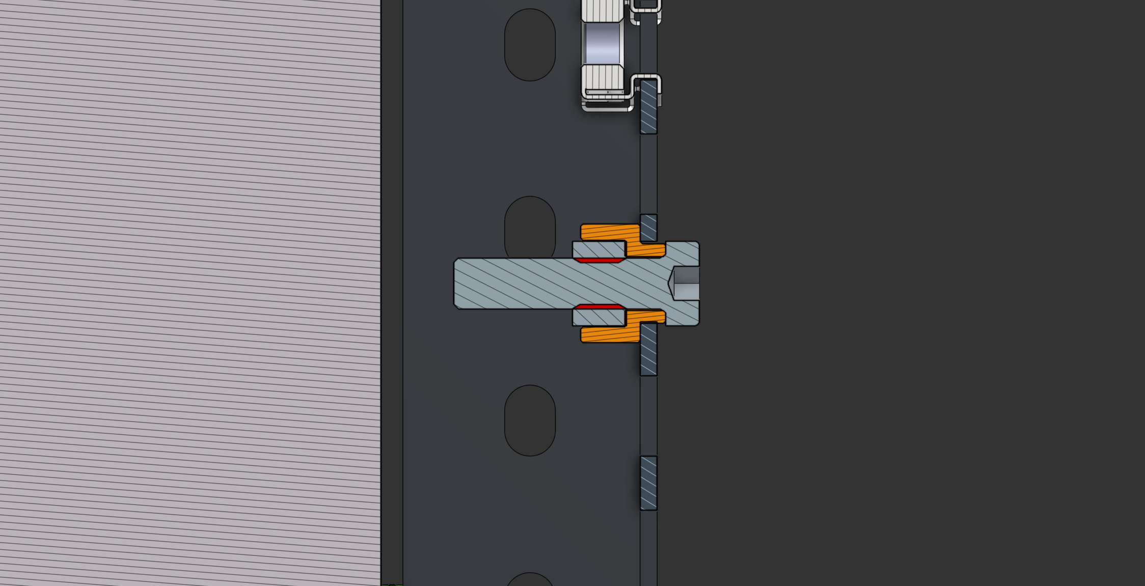 Cage Nut Assembly Section View
Post-Assembly Adjustments & Fixes 🛠️
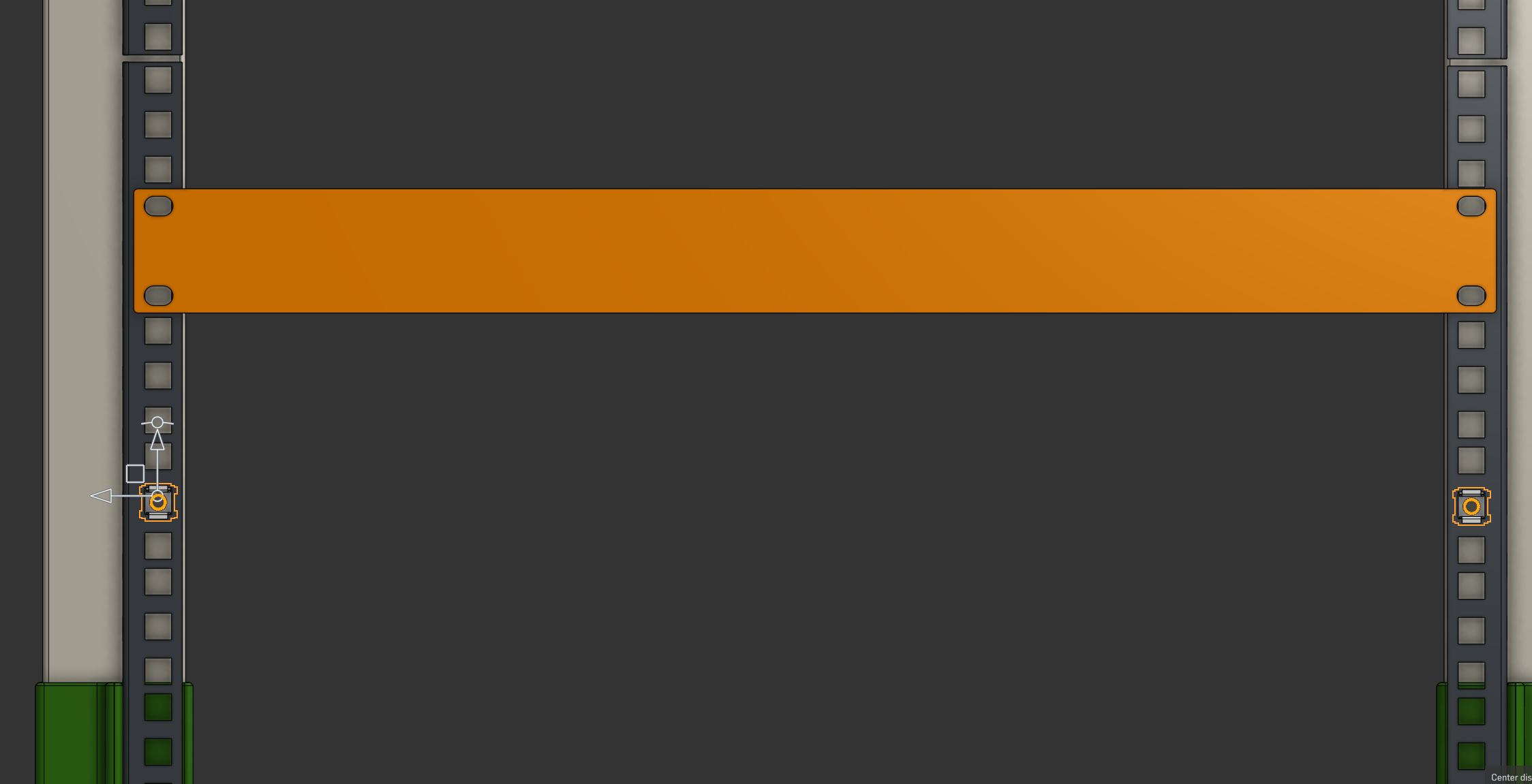
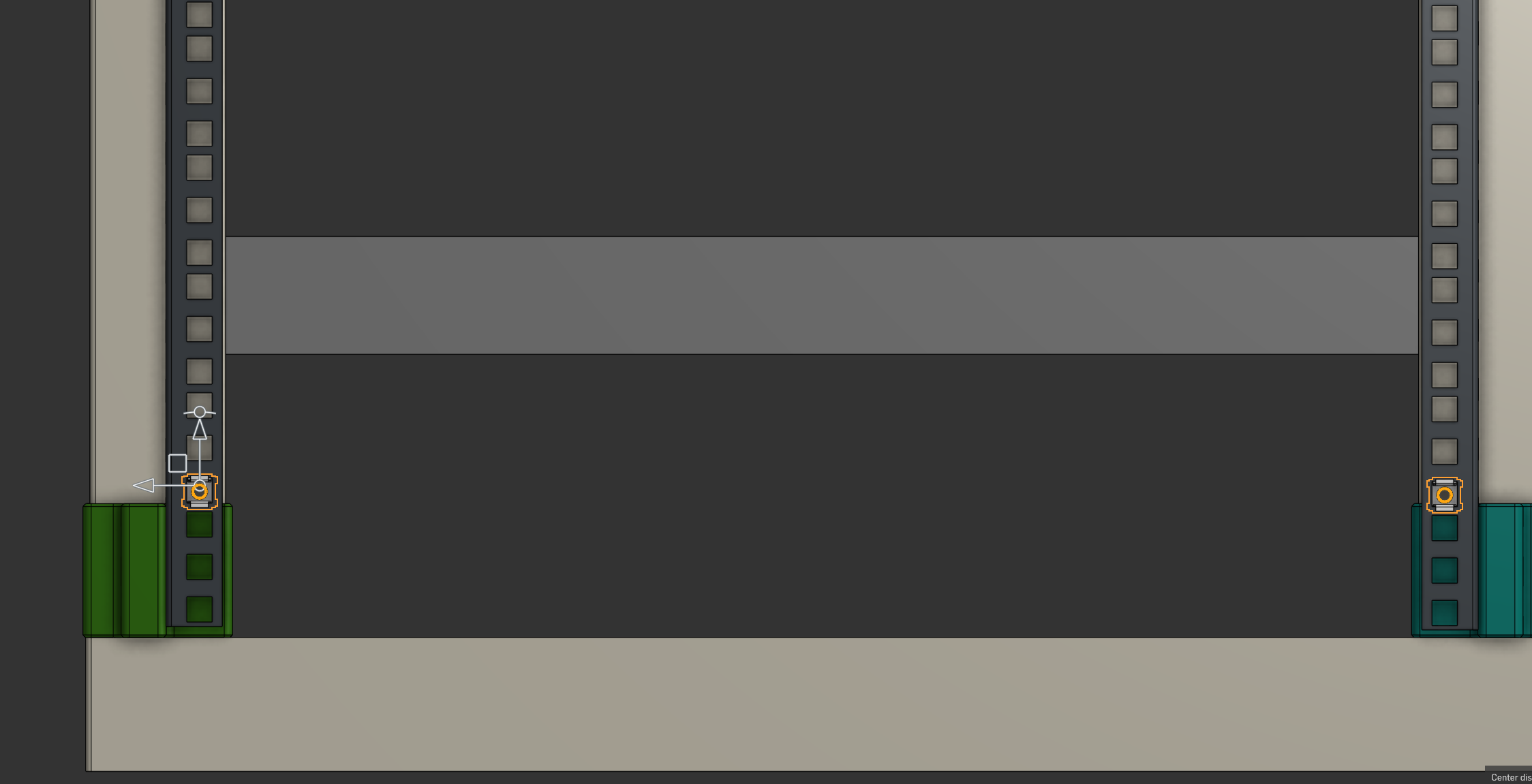
Once one side was fully assembled, I tried to install my Custom 19” Rack Mount for my audio interface, but I quickly encountered an issue:
- The screw holes didn’t align—the rack spacing was insufficient because I didn’t check in the CAD file before launching the print jobs.
In the CAD file, you can measure it more accurately than in real life.
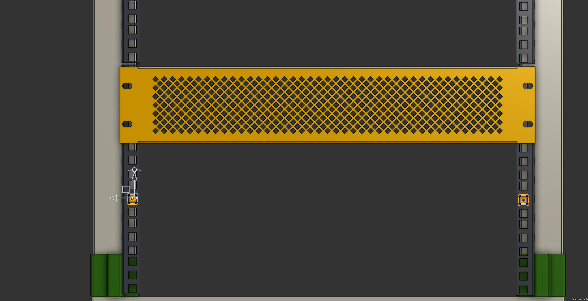 Insufficient Spacing
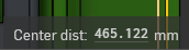
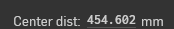 Center Distance Issue
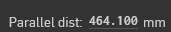 Parallel Distance Alignment
It should be 465.12mm, but it is 454.602mm.
There are two ways to calculate the offset:
Center-to-Center Distance Measurement
\[465.120 - 454.602 = \mathbf{10.518} \text{ mm}\]Parallel Distance Measurement
\[\begin{gather*} 464.100 - 9.50 = 454.60 \text{ mm} \\ 465.12 - 454.60 = \mathbf{10.52} \text{ mm} \\ \implies \boxed{10.518 \text{ mm} \approx 10.52 \text{ mm}} \end{gather*}\]
Now back to the drawing board:
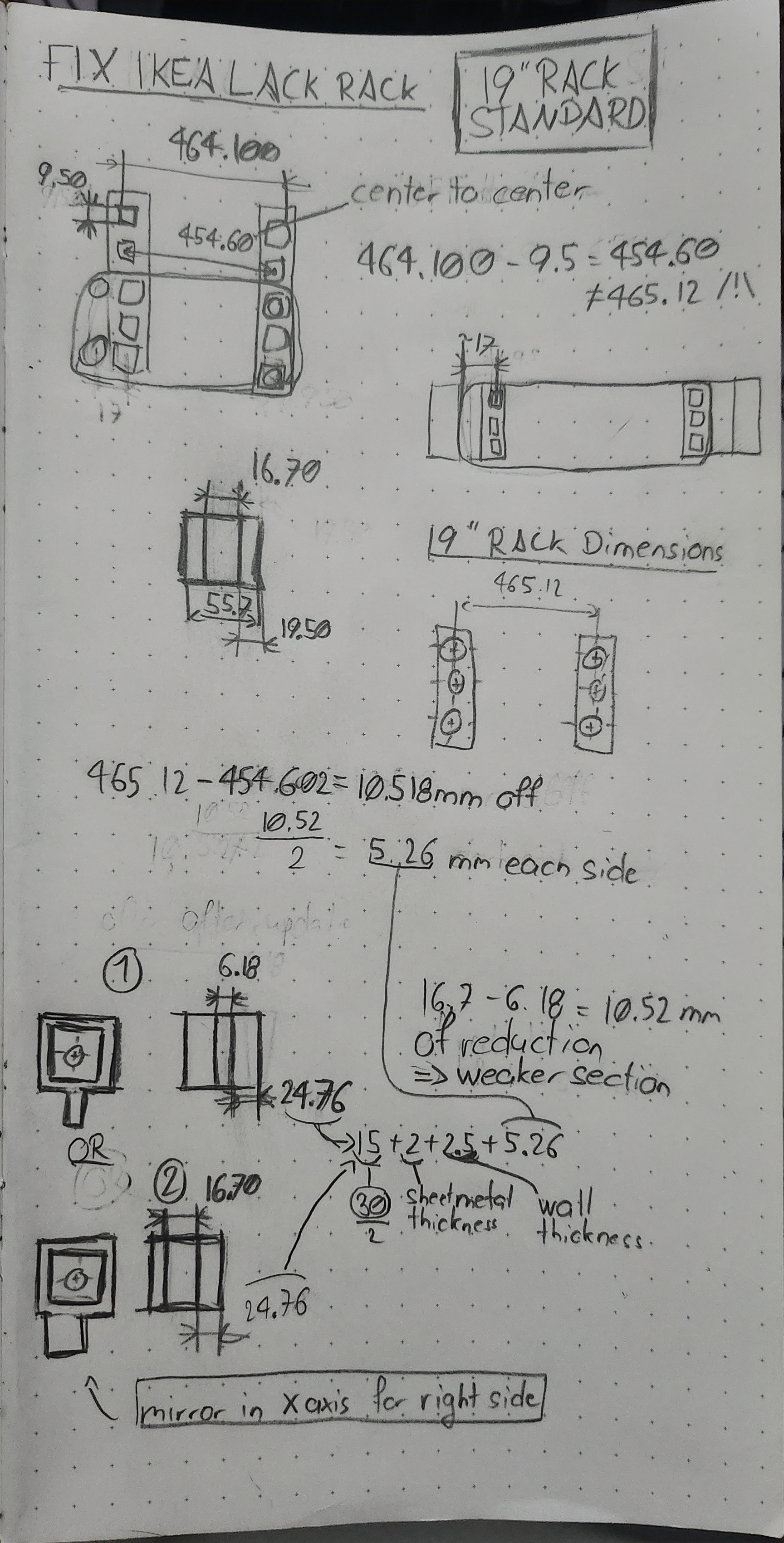 Concept Fix
With the concept clear now, we can go back into CAD and design the two versions of the fix.
Solution 1: Symmetric Design
- Requires x16 of the same piece.
- Thinner screwing thickness → slightly weaker connection.
- Shorter screws needed.
 Solution 1 ISO View
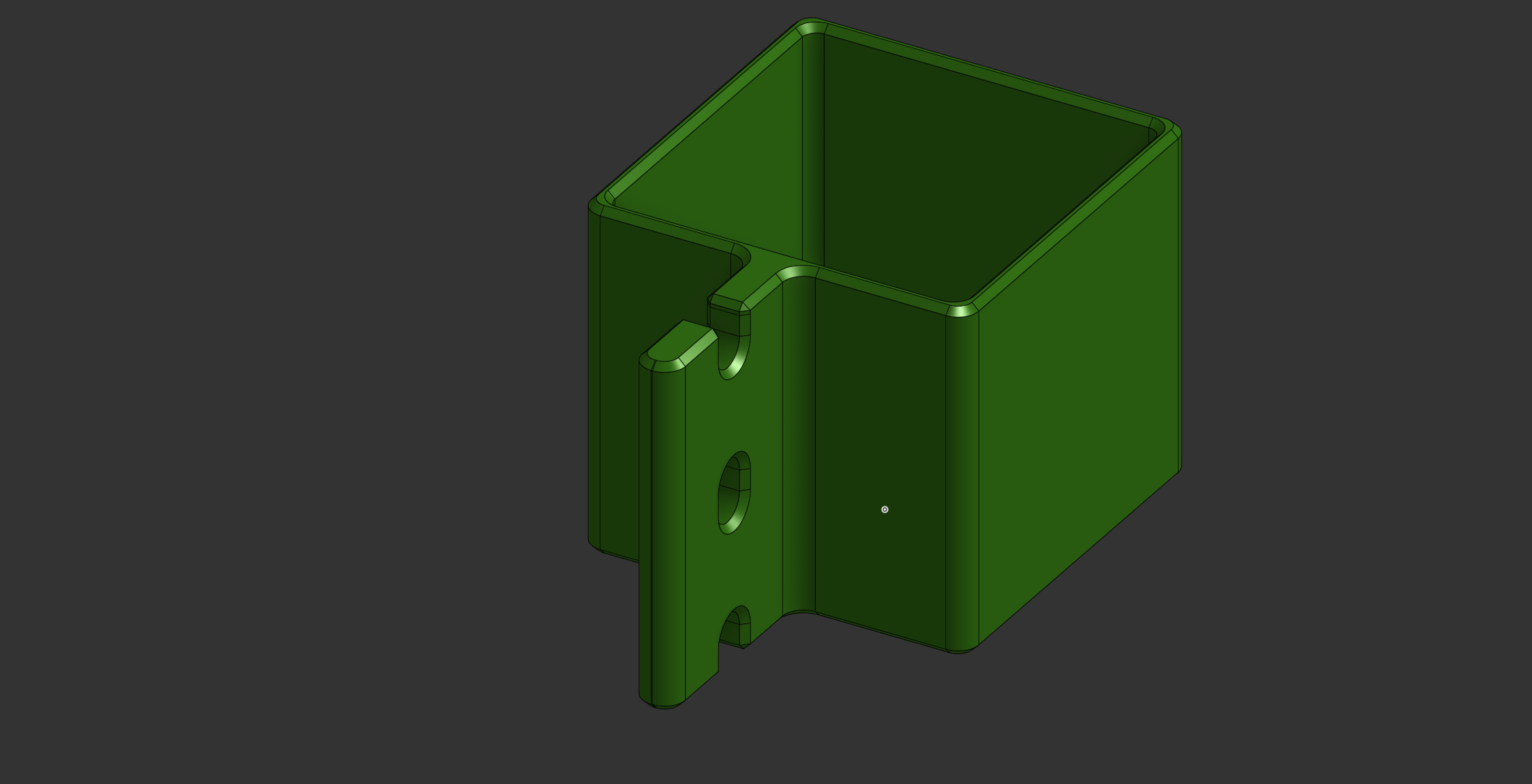
Solution 2: Asymmetric Design
- Requires x8 of each piece (x8 green and x8 blue).
- Same thickness for screw mounting.
- 25mm or longer screws needed.
- More careful assembly required (due to asymmetry).
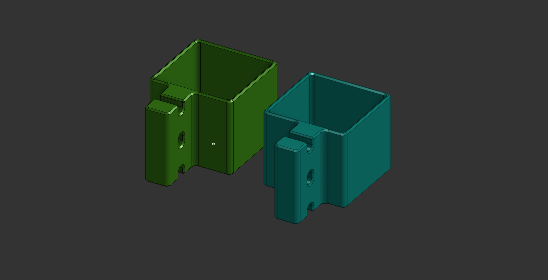 Solution 2 ISO view
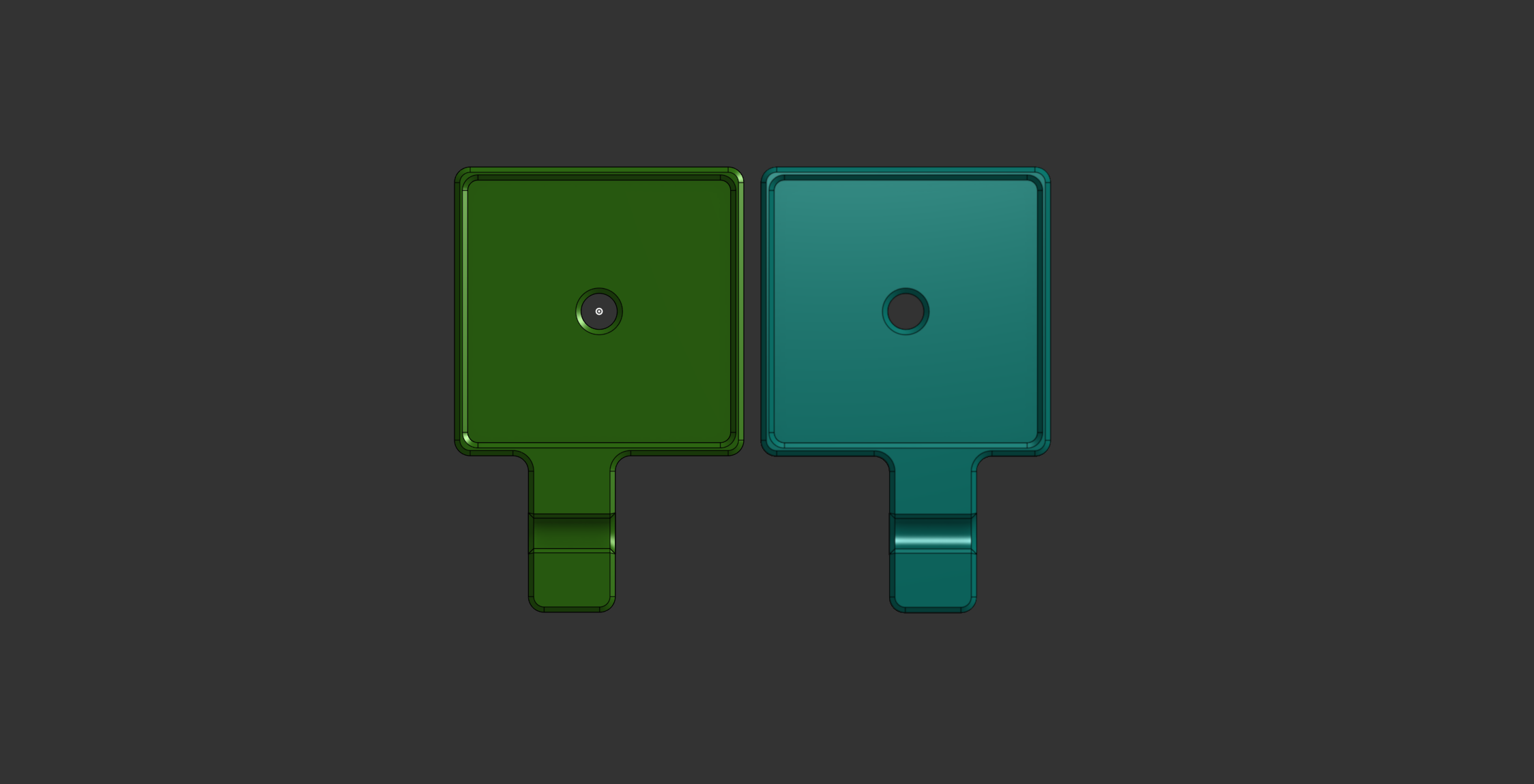 Solution 2 Top View
With the design fix in place, we can verify the spacing in the assembly view.
Solution 1 Verification
 Assembly - Solution 1
 Spacing - Solution 1
 Center Distance - Solution 1
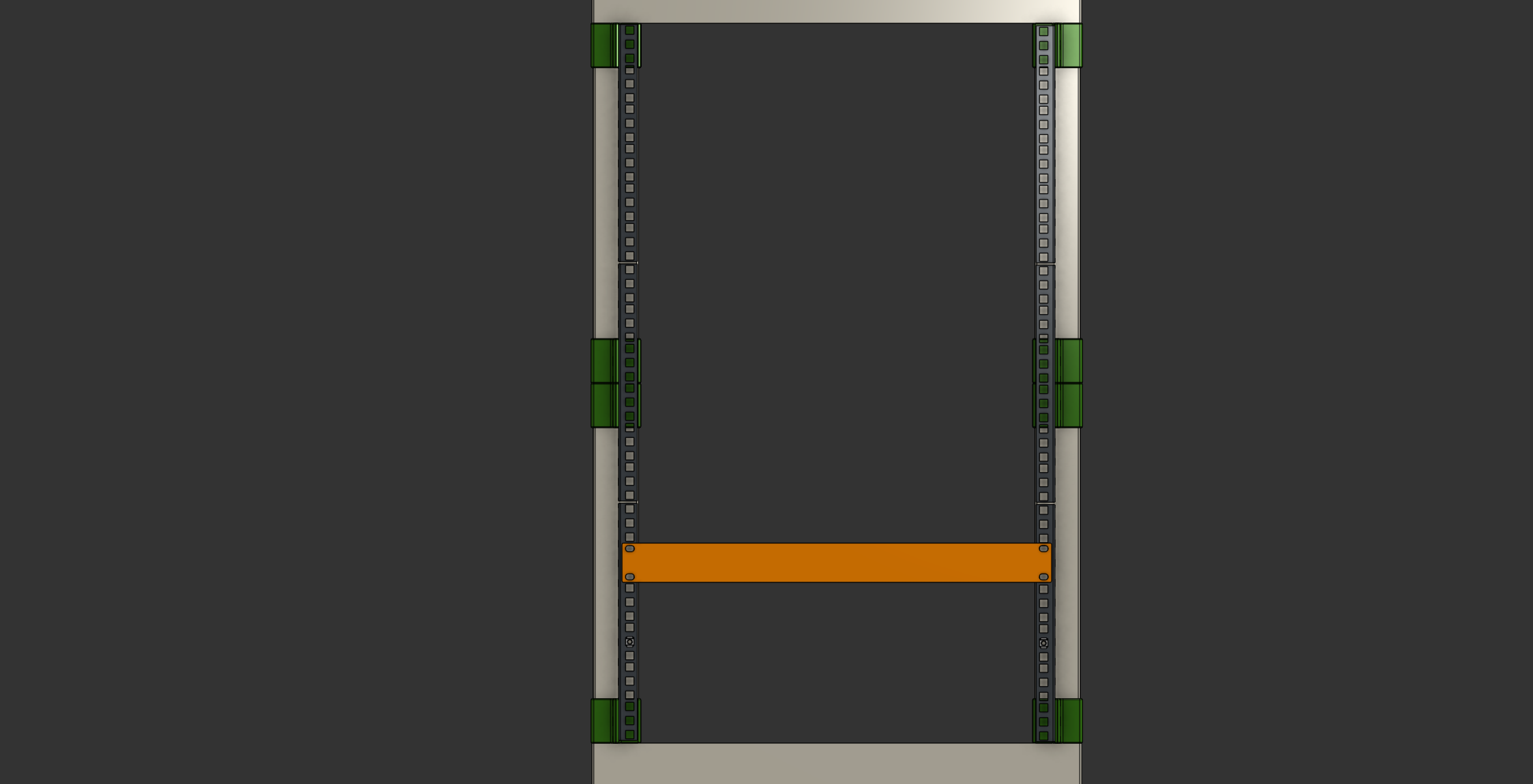
Solution 2 Verification
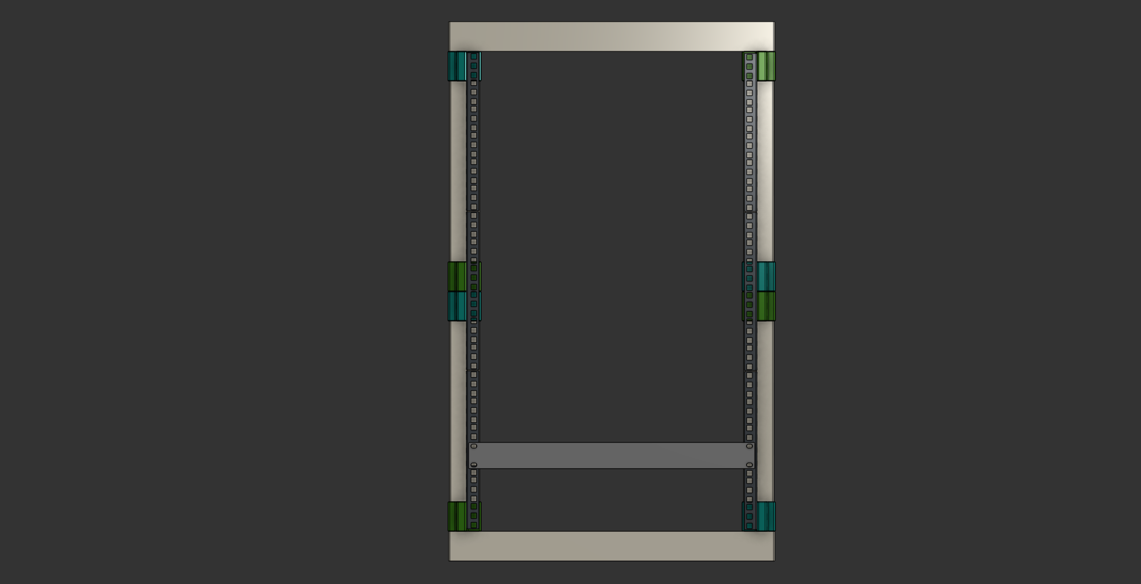 Assembly - Solution 2
Here’s how to assemble the multiple pieces. It does complicate the assembly slightly, but this reference image makes it clearer:
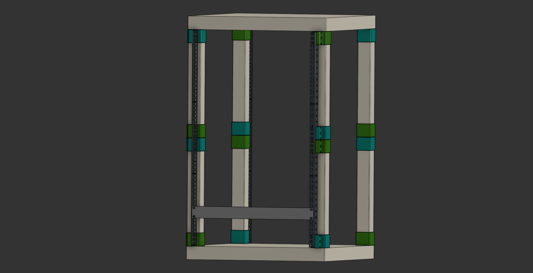 Assembly - Solution 2 ISO View
 Spacing - Solution 2
 Center Distance - Solution 2
There is only 2μm of difference between the two solutions. This difference is so small it can be considered zero.
Print Settings Adjustments
- The print settings remain the same.
- For Solution 1, the Wall Count increases from 6 to 7 for extra strength.
Here’s the completed server rack, featuring Solution 2 for added strength and stability:
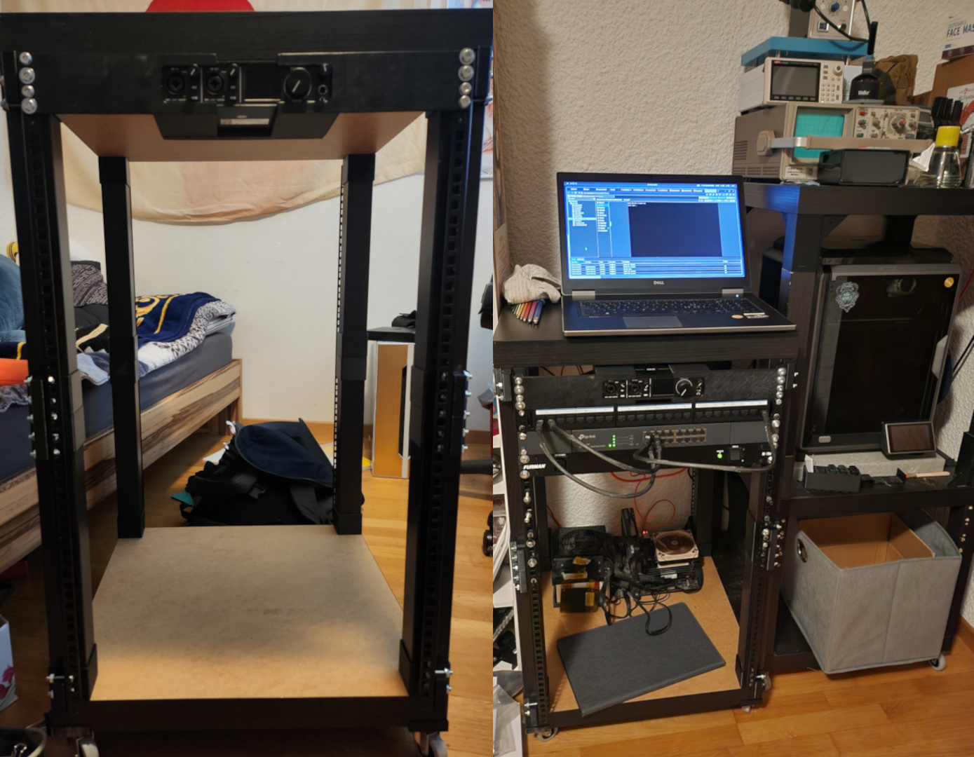 Left Final Rack Assembly, Right Rack in its home
Cost Breakdown 💰
| Item | Quantity | Unit Cost | Total Cost |
|---|---|---|---|
| 3D Filaments | 876.04 g | CHF 30.00/kg | CHF 26.28 |
| Cage Nuts Adapter | 270 g | CHF 30.00/kg | CHF 8.10 |
| Pins | 0.88 g | CHF 30.00/kg | CHF 0.85 |
| (2nd Iteration Solution 1 | 765.04 g | CHF 30.00/kg | CHF 22.95) |
| 2nd Iteration Solution 2 | 869.56 g | CHF 30.00/kg | CHF 26.09 |
| Rack Rails | 4 | CHF 8.30 | CHF 33.20 |
| M6x25 or M6x30 Screws | min. 48, max 264 | CHF 0.20 | CHF 9.60 or CHF 52.80 |
| M6 Nuts | min. 48, max 264 | CHF 0.10 | CHF 4.80 or CHF 26.40 |
| M6 Cage Nuts | max. 216 | CHF 0.60 | CHF 129.60 |
| IKEA Lack | 2 | CHF 9.95 | CHF 19.90 |
| Optional: Casters | 4 | CHF 2.4875 | CHF 9.95 |
| Optional: Woodscrews | 16 | CHF 0.15 | CHF 2.40 |
| Grand Total | CHF 293.52 or CHF 305.87 | ||
| CHF 195.60 or CHF 205.97 |
Explanation of Grand Total (1):
This total includes:
- Total 3D Filaments (for the leg adapter and pins, solution 2 and with the first iteration)
- Rack Rails
- M6 Screws (max quantity)
- M6 Nuts (min quantity)
- M6 Cage Nuts
- IKEA Lack
Optional: Add cost for casters and woodscrews.
Explanation of Grand Total (2):
This total includes:
- Total 3D Filaments (for all parts, solution 2 and with the first iteration)
- Rack Rails
- M6 Screws (max quantity)
- M6 Nuts (max quantity)
- IKEA Lack
Optional: Add cost for casters and woodscrews.
Summary:
- Grand Total (1): CHF 267.24 or CHF 278.59 (with casters and woodscrews without the first iteration)
- Grand Total (2): CHF 167.34 or CHF 179.69 (with casters and woodscrews without the first iteration)
Conclusion 🎯
This was a rewarding project—yes, it was expensive, but now I have an awesome custom rack 😎.
If you’re attempting something similar, remember:
- Research first—you might find existing solutions.
- Stay objective—don’t let emotions rush your process.
- Test measurements in CAD before printing.