Designing a Custom Rack Mount for an Audio Interface
Introduction
When setting up a professional or home studio, organization is key. Rack-mounted audio equipment not only saves space but also improves accessibility and cable management. In this project, I’ll walk you through designing and building a custom rack mount for an audio interface.
Sketching the Concept ✏️
Before jumping into CAD software, I started with hand-drawn sketches to visualize:
- How the audio interface fits inside the rack.
- Mounting points for screws and brackets.
Here’s an early concept:
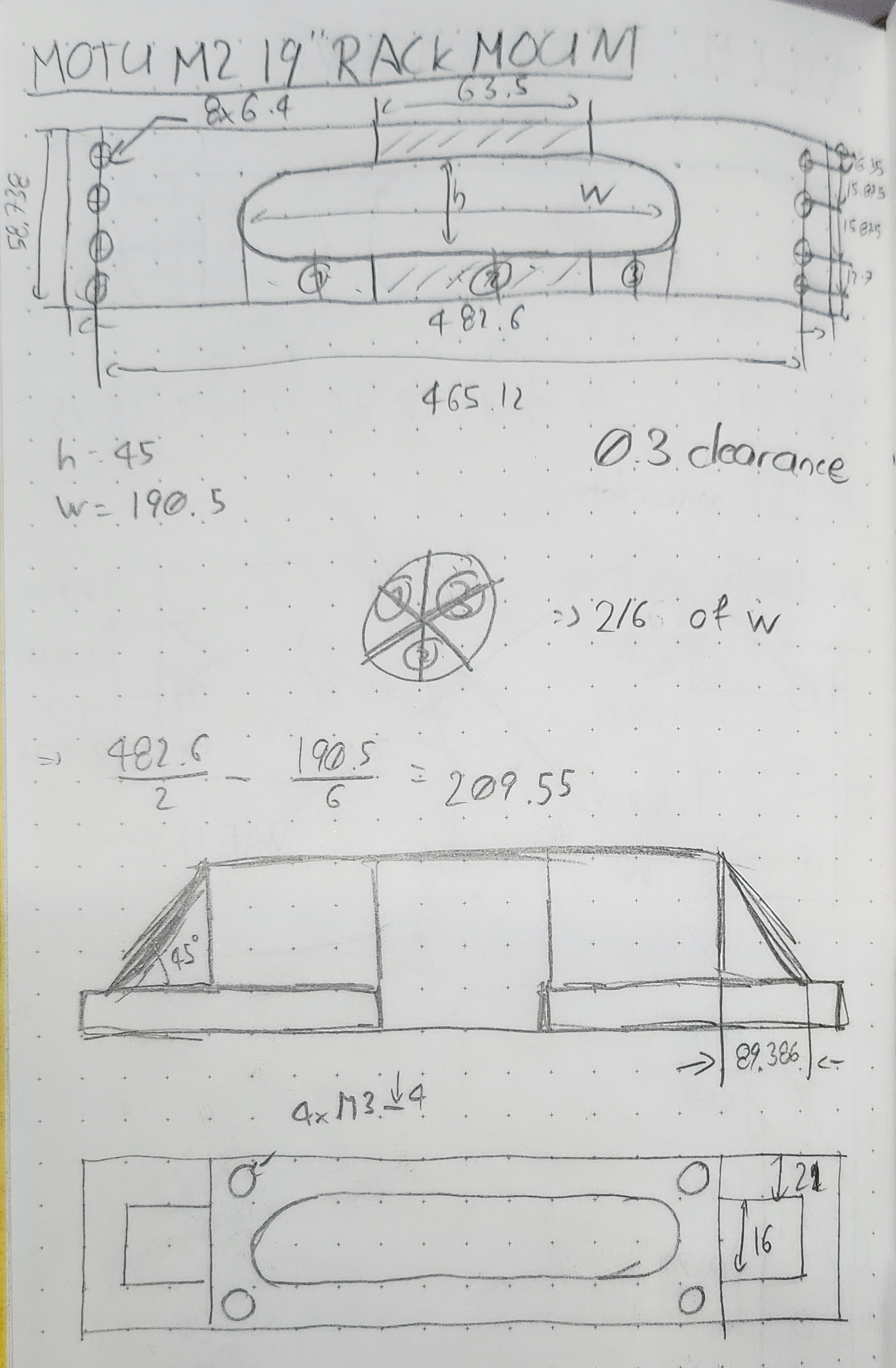 Initial Hand-Drawn Sketch
Materials & Tools Needed 🛠️
| Tools | Materials |
|---|---|
| Writing Instruments and Paper | 3D Filaments |
| Extrait de Normes 2022 (VSM) | M3x30 Countersunk Screws |
| Measuring Tools (Ruler, Caliper) | M3 Threaded Insert |
| CAD Software | |
| Google Machine | |
| 3D Printer | |
| Screwdrivers | |
Designing & Prototyping 🖥️
Key design considerations:
✔ Exact dimensions of the audio interface.
✔ Mounting brackets must fit a 19” rack seamlessly.
✔ Reversible: The solution should avoid modifications to the interface.
✔ Easily reproducible: The design should not require specialized tools not major modification.
Using the manufacturer’s dimensions and referencing standards like 19-inch rack specifications, I began the CAD work. Here are two reference drawings I relied on:
 source: fr.wikipedia.org
 source: en.wikipedia.org
With these references, I created the rack mount design while adhering to mechanical standards.
Pro Tip: Find CAD files of the object you’re designing for whenever possible—it saves time and improves accuracy.
Here’s the main sketch:
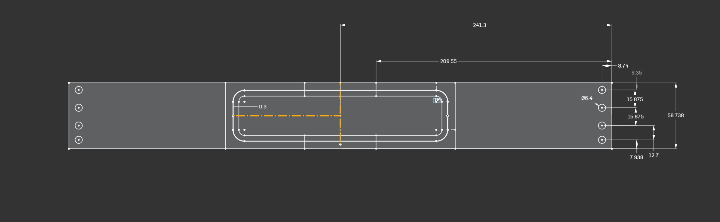 Main Sketch with Symmetry Axes Highlighted
Pro Tip: Use the Mirror function for symmetrical designs to save time and effort.
And here’s the result:
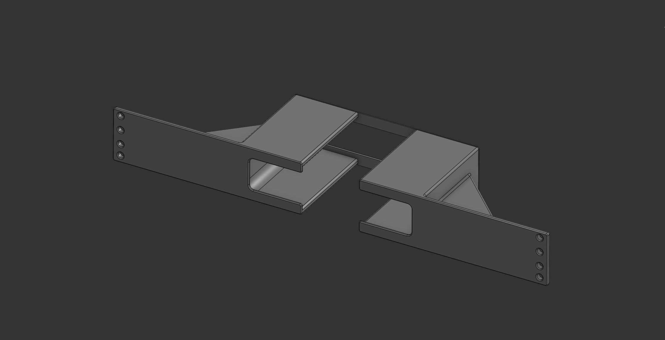 First Prototype
Prototypes & Adjustments
After assembling the prototype, I discovered a few issues:
- No clearance for the interface.
- Rubber feet on the device weren’t accounted for.
Here’s how I fixed these issues:
- Updated the model to include the rubber feet.
- Added grooves on the enclosure for better fit.
- Introduced a 0.3mm offset where the enclosure nests the interface.
 Grooves Added in the First Iteration
Pro Tip: For grooves, use the Boolean function in CAD software, but ensure you have a model of the object.
Subsequent testing revealed another issue:
- The rubber feet hit the back of the enclosure, preventing the interface from sliding in.
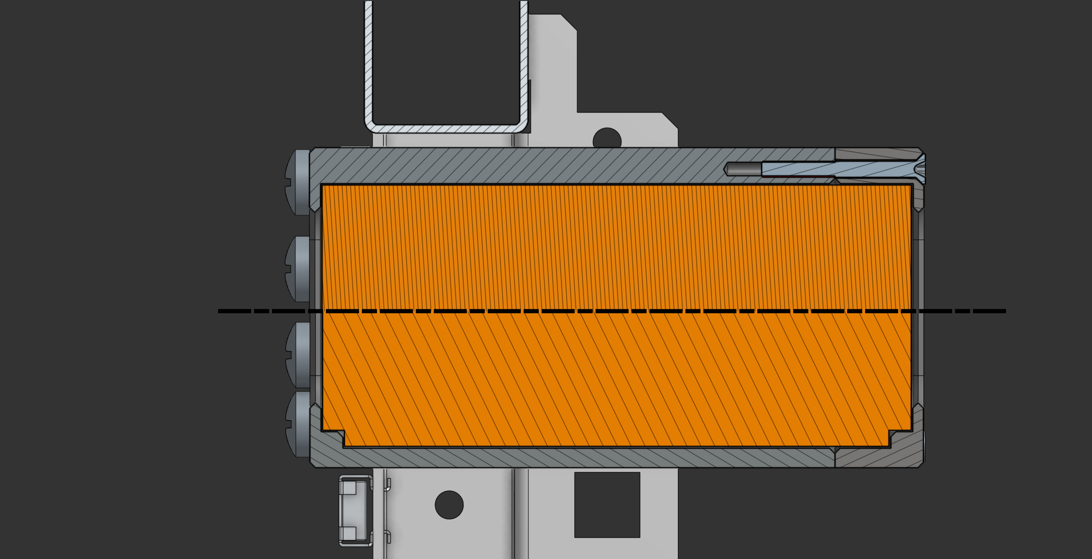
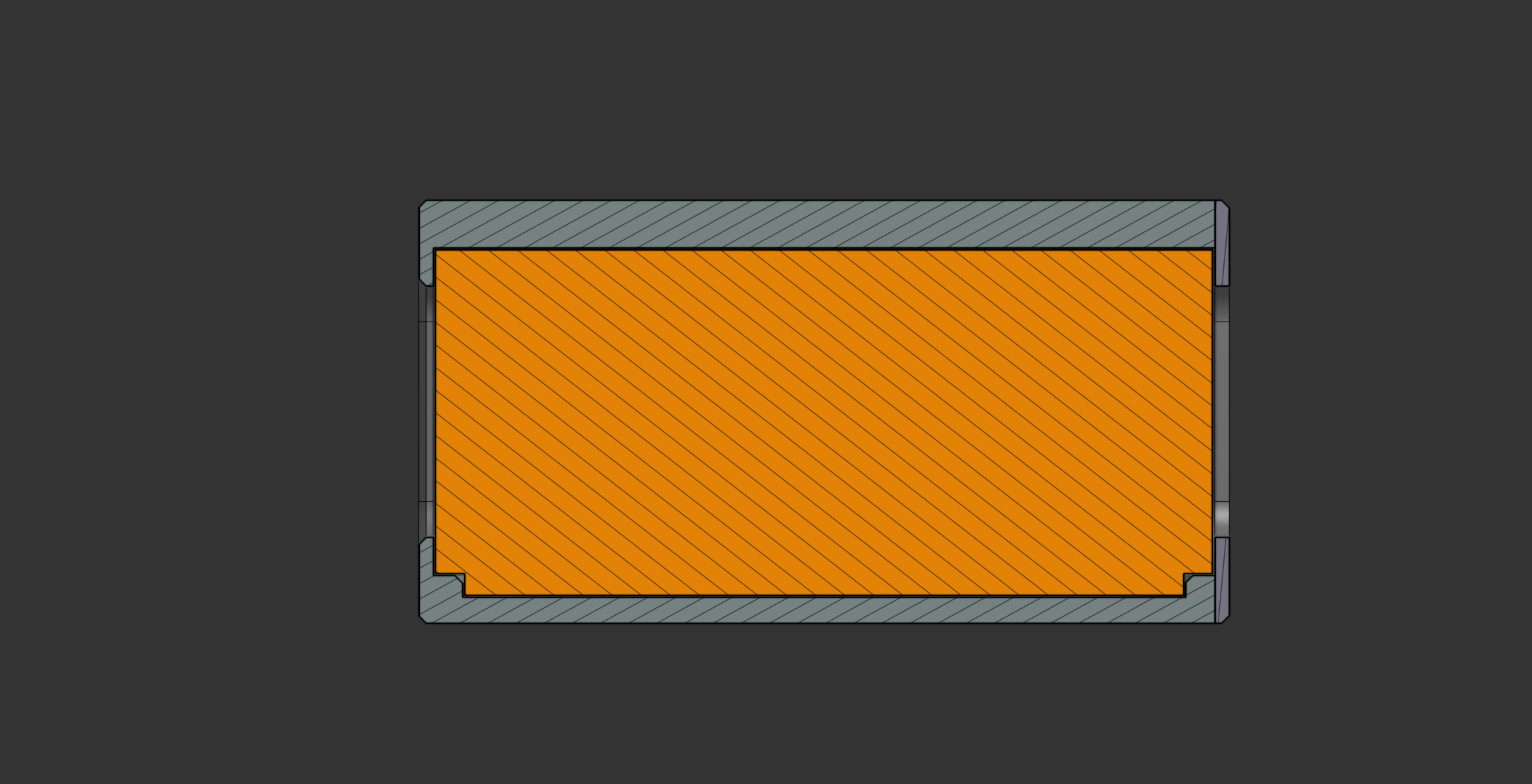 Section View from the First Iteration
To resolve this, I:
- Extended the backplate and switched to longer M3x30 screws.
- Optimized how the backplate attaches to the chassis.
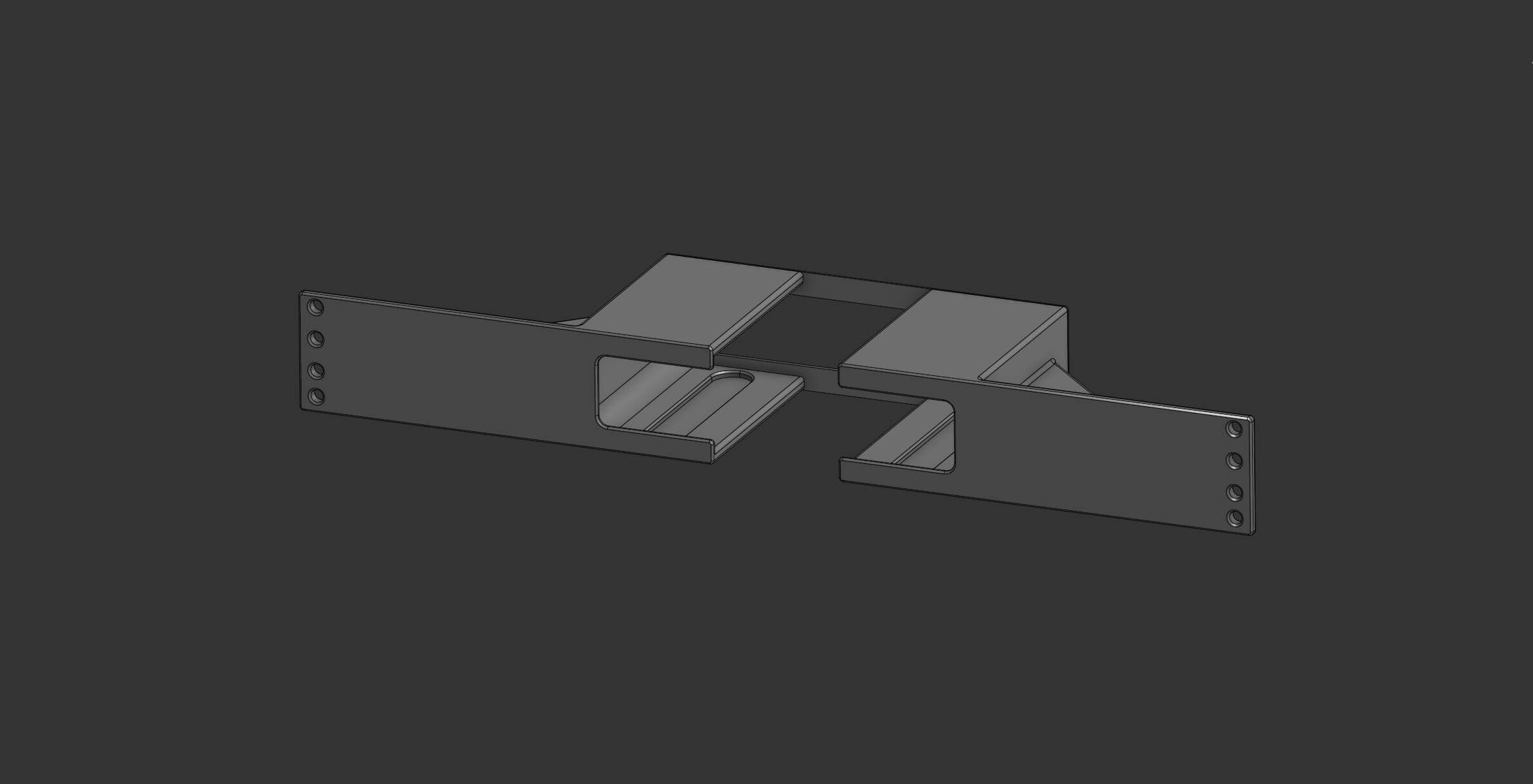
Here’s the rendered model after all adjustments:
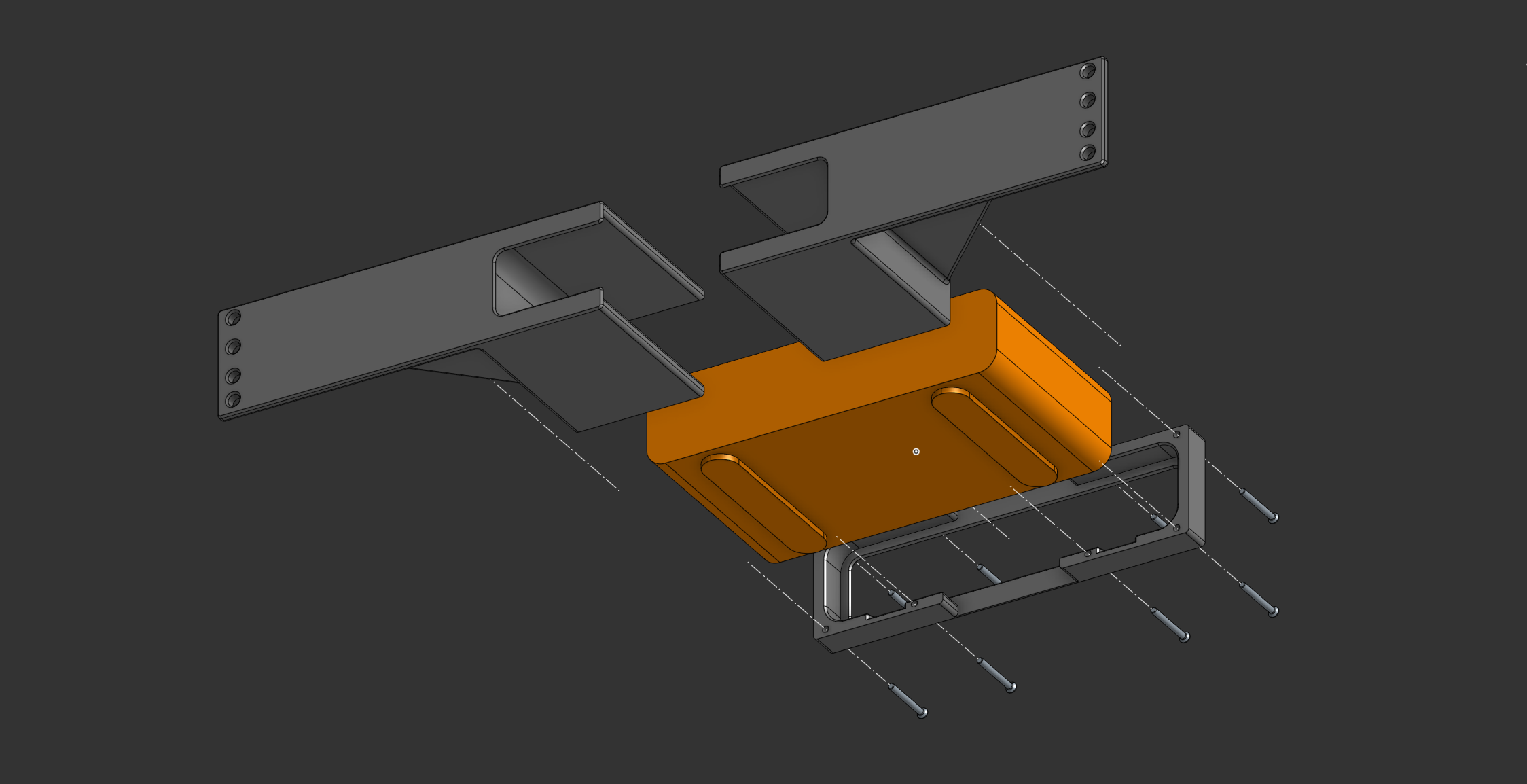 Exploded View of Final Version
Final Assembly & Installation 🔩
With the rack mount completed, I tested the design using CAD models of a 19” server rack and M6 cage nuts.
Here’s the final assembly:
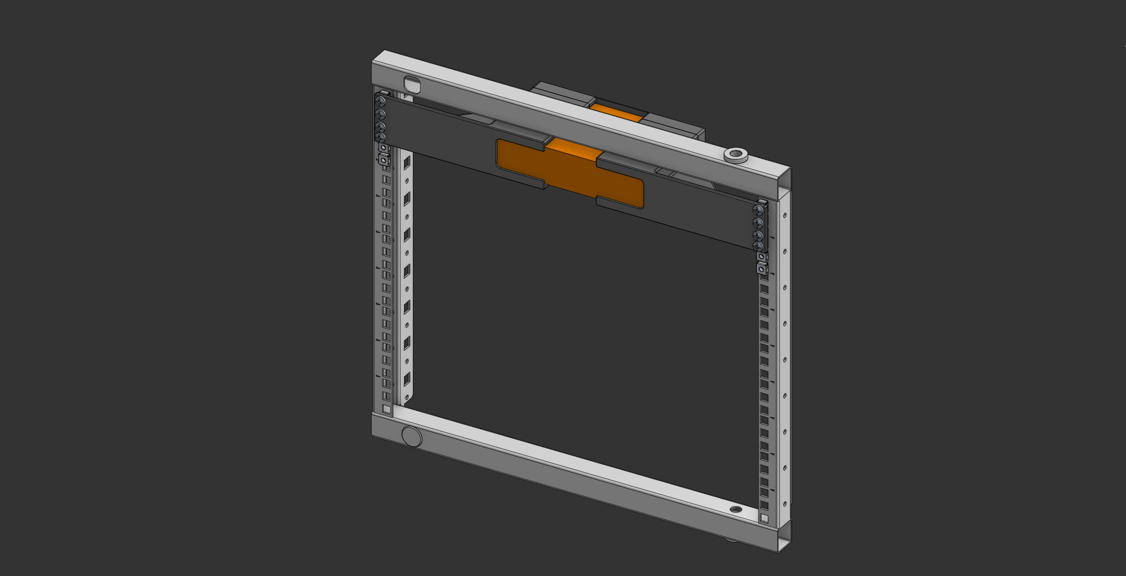 Assembly in 19” Rack
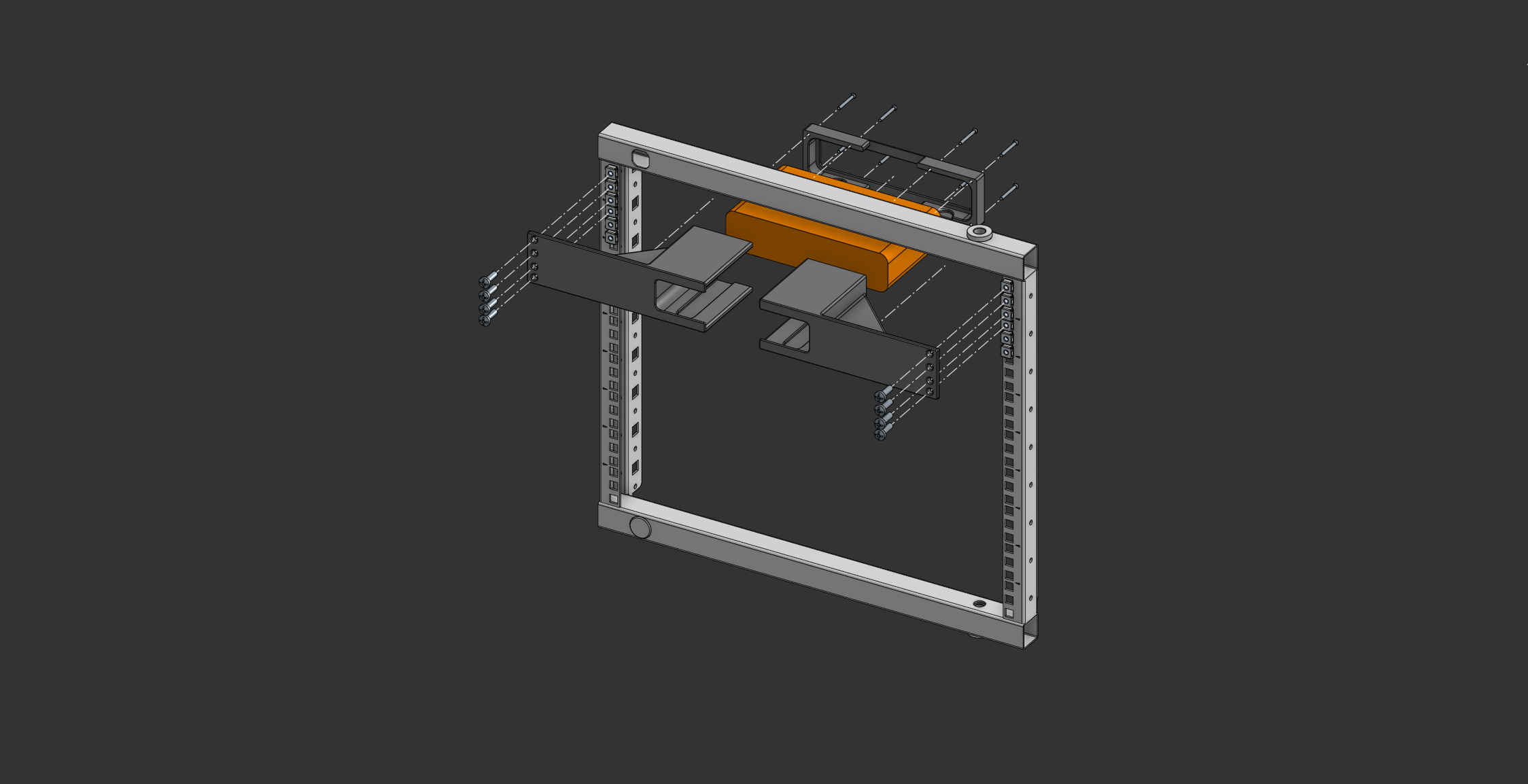 Exploded View of the Assembly
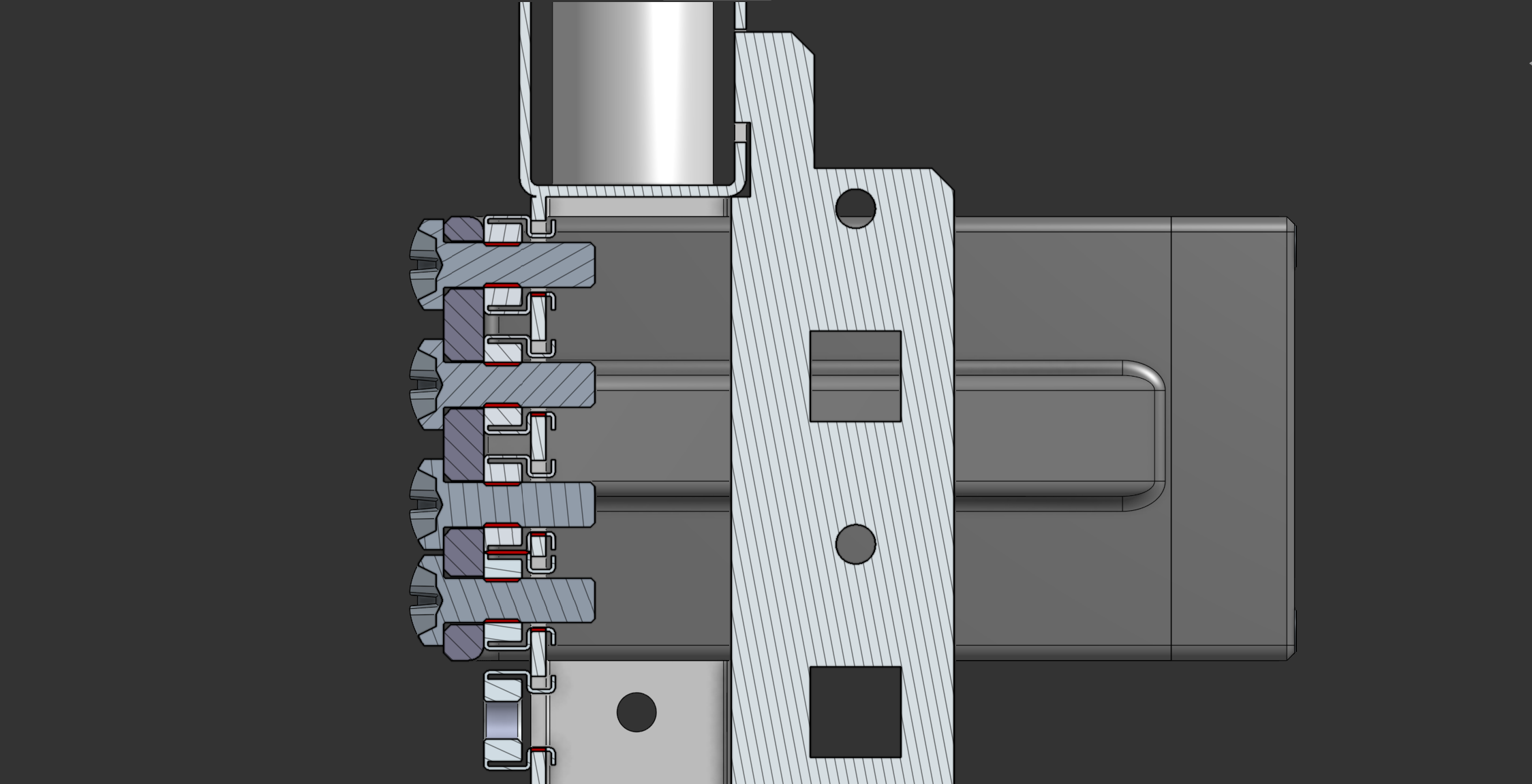 Section View Showing Screw Alignment
 Custom Section View Showing Backplate Alignement
3D Printing
Printing Settings:
| Setting | Value/Parameter |
|---|---|
| Print Material | PETG |
| Layer Height | 0.2 [mm] |
| Infill Density | 15% |
| Infill Pattern | Cross Hatch |
| Wall Count | 3 |
| Top Layers Count | 3 |
| Bottom Layers Count | 3 |
| Support Structures | NO |
| Brim or Raft | NO |
Note: PLA can also be used but ensure it can withstand the heat generated by rack-mounted equipment.
Post-Print Adjustments 🛠️
Once printed, I began assembling the rack mount and quickly encountered an issue:
- The backplate was too thin, making it difficult to secure.
- While attempting to tap the holes, my tap broke (the set of taps cost me 20 CHF—I wasn’t expecting much from it).
- Screwing the backplate was a pain due to the lack of proper threading.
To fix this, I modified the design and added threaded inserts, making assembly much easier.
Here’s a section view of the modified backplate:
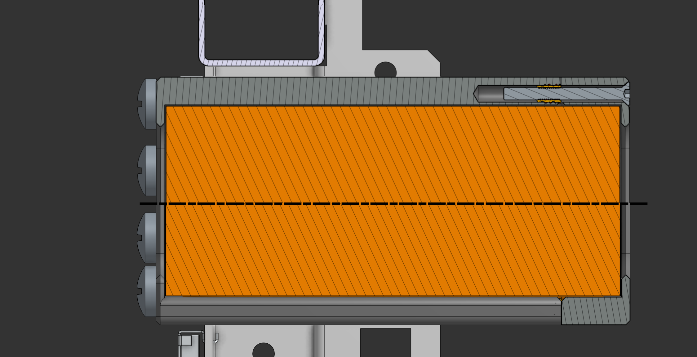 Custom Section View Showing the Fixes
And here’s the finished rack mount:
<Insert Image of Final Printed Model>
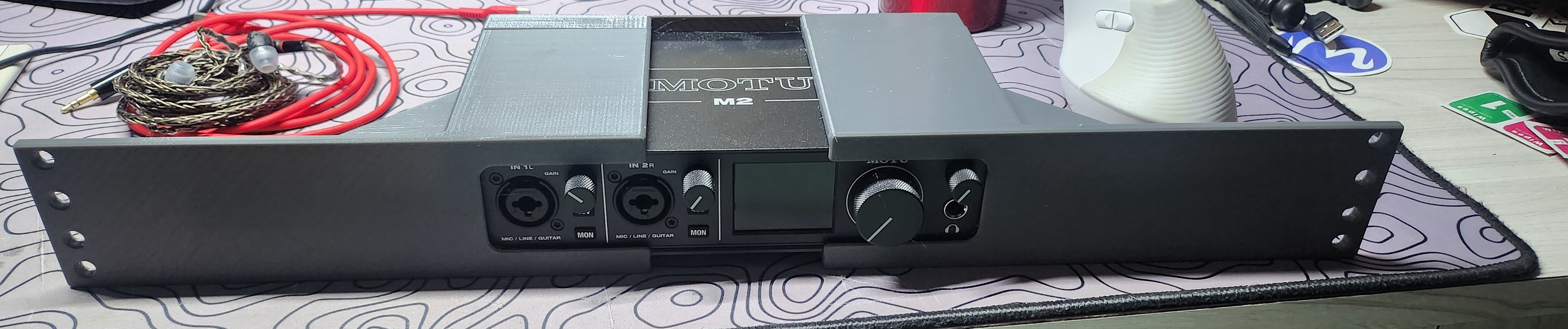 Final Printed Model
Cost Breakdown 💰
| Item | Quantity | Unit Cost | Total Cost |
|---|---|---|---|
| 3D Filaments | 290.98 g | CHF 30.00/kg | CHF 8.73 |
| 2nd Iterations | 314.47 g | CHF 9.43 | |
| M3x30 Countersunk Screws | 8 pieces | CHF 0.10 | CHF 0.80 |
| M3 Threaded Insert | 8 pieces | CHF 0.10 | CHF 0.80 |
| Grand Total | CHF 19.76 |
Conclusion 🎯
Building this custom rack mount was a rewarding challenge. I refined my CAD skills, learned new techniques, and created something functional and aesthetically pleasing.
If you’re considering a similar project, here are some tips:
- Start Small: Use cardboard for templates before committing to CAD.
- Measure Twice: Precision is key when working with racks.
- Test Fit: Ensure the design works with actual hardware before finalizing.
- Embrace Iteration: Every failure is a learning opportunity.
- Enjoy the Process: Perfection isn’t necessary—focus on progress and learning.